Video signal transmission clock generation device and method

A video clock and video signal technology, applied to electrical components, power automatic control, instruments, etc., can solve problems such as inability to switch flexibly

Active Publication Date: 2018-05-08
WUHAN JINGLI ELECTRONICS TECH
View PDF6 Cites 11 Cited by
  • Summary
  • Abstract
  • Description
  • Claims
  • Application Information

AI Technical Summary

Problems solved by technology

However, when the existing image signal generating equipment is powered on, the field frequency and image clock of the output image are fixed and cannot be switched flexibly. Therefore, a device that can flexibly adjust the output clock frequency and phase according to the configuration is needed to meet LCD module testing requirements

Method used


Image

  • Video signal transmission clock generation device and method

Examples


Embodiment Construction

[0052] In order to make the object, technical solution and advantages of the present invention clearer, the present invention will be further described in detail below in conjunction with the accompanying drawings and embodiments. It should be understood that the specific embodiments described here are only used to explain the present invention, not to limit the present invention. In addition, the technical features involved in the various embodiments of the present invention described below can be combined with each other as long as they do not constitute a conflict with each other.

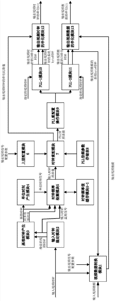
[0053] The video signal transmission clock generation device provided by the embodiment is realized based on FPGA, specifically refer to figure 1 , including video data conversion module 1, input clock stabilization module 2, reference clock generation module 3, unit time generation module 4, clock frequency detection module 5, upper layer configuration module 6, clock reconfiguration module 7, ...


PUM


Abstract

The invention discloses a video signal transmission clock generation device and method. The device has a video clock interface, a video data interface, a configuration parameter interface, an input clock frequency accurate detection unit, an upper configuration module and a clock reconfiguration unit. The input clock frequency accurate detection unit generates a reference clock, carries out stabilization, phase modulation, clock domain adjustment and frequency doubling on a received input video clock to generate a synchronous detection clock, generates a unit time signal according to the reference clock, and detects and obtains an input clock frequency value according to the reference clock, the synchronous detection clock and the unit time signal when there is a continuous and stable video clock input. The parameters of upper configuration are obtained through the configuration parameter interface, and clock reconfiguration is carried out according to the configuration parameters, a pre-stored PLL parameter table and the input clock frequency value to obtain a configurable video signal transmission clock. Through the device and the method, a video signal transmission clock with the frequency and phase configured flexibly can be obtained according to the video signal clock input at any frequency and the demand.

Description

technical field [0001] The invention belongs to the technical field of liquid crystal module detection, and in particular relates to a video signal transmission clock generation device and method. Background technique [0002] When inspecting LCD modules in the production line, it is often necessary to detect the dot screen effect of the module under different field frequencies and different image clock frequencies, and frequently switch between different field frequencies and clock frequencies. However, when the existing image signal generating equipment is powered on, the field frequency and image clock of the output image are fixed and cannot be switched flexibly. Therefore, a device that can flexibly adjust the output clock frequency and phase according to the configuration is needed to meet LCD module testing requirements. Contents of the invention [0003] In view of the above defects or improvement needs of the prior art, the present invention provides a video sign...

Claims


Application Information

Patent Timeline
Patent Type & Authority Applications(China)
IPC IPC(8): G09G3/00H03L7/083
CPCG09G3/006H03L7/083
Inventor 朱亚凡许恩
Owner WUHAN JINGLI ELECTRONICS TECH
Why Eureka
Try Eureka