Ball-joint-based pneumatic manipulator

A technology of ball joints and operating arms, which is applied in medical science, surgery, surgical instrument support, etc., can solve the problem that the attending doctor cannot operate multiple surgical instruments at the same time, so as to improve the stability of surgery, reduce the probability of error, and reduce labor. intensity effect

Pending Publication Date: 2018-05-11
HARBIN INST OF TECH SHENZHEN GRADUATE SCHOOL
View PDF2 Cites 4 Cited by
  • Summary
  • Abstract
  • Description
  • Claims
  • Application Information

AI Technical Summary

Problems solved by technology

[0004] The purpose of the present invention is to solve the problem that the attending doctor cannot operate multiple surgical instruments at the same time in medical operations, and invented an operating arm capable of positioning surgical instruments

Method used


Image

  • Ball-joint-based pneumatic manipulator
  • Ball-joint-based pneumatic manipulator
  • Ball-joint-based pneumatic manipulator

Examples


Embodiment 1

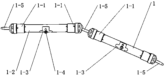
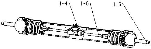
[0030] Such as Figures 1 to 3 As shown, a pneumatically operated arm based on a ball joint includes a connecting rod 1 and a joint connecting rod 1-5, wherein the joint connecting rod 1-5 is connected to the ball joint mechanism module 1-1 of the connecting rod 1 , the connecting rod 1 includes a ball joint mechanism module 1-1, a connecting cylinder 1-2, a cover plate 1-3, a three-way joint 1-4, and an air pipe 1-6, and the two ends of the connecting cylinder 1-2 A ball joint mechanism module 1-1 is installed respectively, and the three-way joint 1-4 is installed inside the connecting cylinder 1-2. The other end of 1-4 passes through the cover plate 1-3, and the cover plate 1-3 is installed on the connecting cylinder 1-2, and the cover plate 1-3 locks the tee joint 1-4 in the connecting cylinder 1-2; pneumatic operation The connecting rod 1 of the arm is connected by two ball joint mechanism modules 1-1 at both ends of the hollow connecting cylinder 1-2, and the two ends of...

Embodiment 2

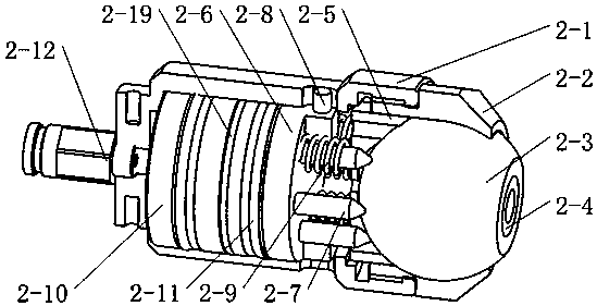
[0038] Such as Figure 4 As shown, this embodiment is obtained by transforming the head end form of the ejector rod 2-7 in the first embodiment on the basis of the first embodiment, for example, transforming the coaxial conical surface in the first embodiment into a The -7 axis is formed by a curved surface with a certain eccentricity Figure 4 The eccentric push rod 2-13 of (a). Or retain the outer surface of the ejector rod 2-7, and remove the material of the ejector rod 2-7 from the outside to the inside to form Figure 4 Concave ejector pin 2-14 shape in (b). Other unmentioned components are the same as those in Embodiment 1 without change.

Embodiment 3

[0040] Such as Figure 5 As shown, this embodiment is obtained on the basis of Embodiment 1. What is changed in this embodiment is that the numbers of guide rods and springs are arranged uniformly or non-uniformly, while other parts and structures are the same as Embodiment 1. Illustrate as: by changing the kind or the quantity of guide rod 2-7, eccentric push rod 2-13, concave push rod 2-14 installed on the front piston 2-6. E.g Figure 5 (a) three guide rods 2-7 and corresponding springs 2-9 are installed; Figure 5 Four guide rods 2-7 and corresponding springs are installed in (b). Figure 5 (a) shows a uniform arrangement by changing the number of guide rods and springs; Figure 5 (b) shows that the number of guide rods and springs is changed for non-uniform arrangement.


PUM


Abstract

The invention discloses a ball-joint-based pneumatic manipulator. The manipulator is composed of a connecting rod and a joint connecting rod, wherein a ball joint mechanism module is arranged at eachof two ends of a connecting rod connection cylinder; and two ends of the joint connecting rod are respectively connected with the ball joint mechanism module of the connecting rod so as to form the manipulator. The ball-joint-based pneumatic manipulator disclosed by the invention has the beneficial effects that surgical tools and appliances can be located in a three-dimensional space, high appliance positioning stability and positioning accuracy can be provided during the operation, a doctor is not tired while operating for a long time, and the labor intensity of the doctor is alleviated. Withrespect to a patient, the operative stability is improved, and the error probability caused by instable operations of the surgical instruments is reduced. For different surgical tools, a load relationship between the manipulator and the surgical instruments can be dynamically adjusted by adjusting spring parameters and compressed gas pressures, and multiple operation needs are met.

Description

technical field [0001] The invention belongs to the field of medical equipment, and in particular relates to a pneumatic operating arm based on a ball joint. Background technique [0002] China's medical costs are rising rapidly. In medical operations, usually a single doctor cannot complete surgical tasks independently. Due to the use of multiple instruments in the operation, doctors cannot operate these instruments at the same time, and need additional assistants to assist them to complete the operation. Due to the existence of the assistant doctor, the attending doctor needs to communicate with the assistant to allow the assistant to move the device to the designated position. If the communication link is not clear, the operation time will be prolonged. In addition, the assistant has the problem of unstable positioning of the device when working for a long time, so it is necessary A surgical instrument positioning device capable of stable positioning and quickly according...

Claims


Application Information

Patent Timeline
IPC IPC(8): A61B90/50A61B34/00
CPCA61B34/70A61B90/50
Inventor 李鹏
Owner HARBIN INST OF TECH SHENZHEN GRADUATE SCHOOL
Why Eureka
Try Eureka