A high-efficiency mixer

A mixer, high-efficiency technology, applied to mixer accessories, mixers with rotating agitation devices, mixers, etc., can solve problems such as low efficiency, dust pollution, and worker hazards, and achieve improved work efficiency, increased mixing speed, and high efficiency The effect of stirring

Active Publication Date: 2020-11-06
GUANGZHOU RUXING TECH DEV +2
View PDF6 Cites 0 Cited by
  • Summary
  • Abstract
  • Description
  • Claims
  • Application Information

AI Technical Summary

Problems solved by technology

[0003] The paddle structure of common mixers currently on the market is single, which cannot cope well with the mixing of powder and slurry, and the efficiency is low; during the mixing process, the material is completely exposed to the air, and the paddle liquid is easy to volatilize and generate organic gas, and powder is prone to occur Raised dust pollution, causing harm to the staff; traditional mixers need to be manually controlled, and the work efficiency is low

Method used


Image

  • A high-efficiency mixer
  • A high-efficiency mixer
  • A high-efficiency mixer

Examples


Embodiment Construction

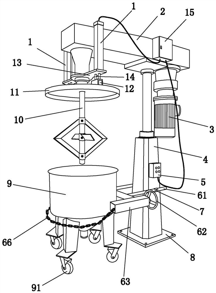
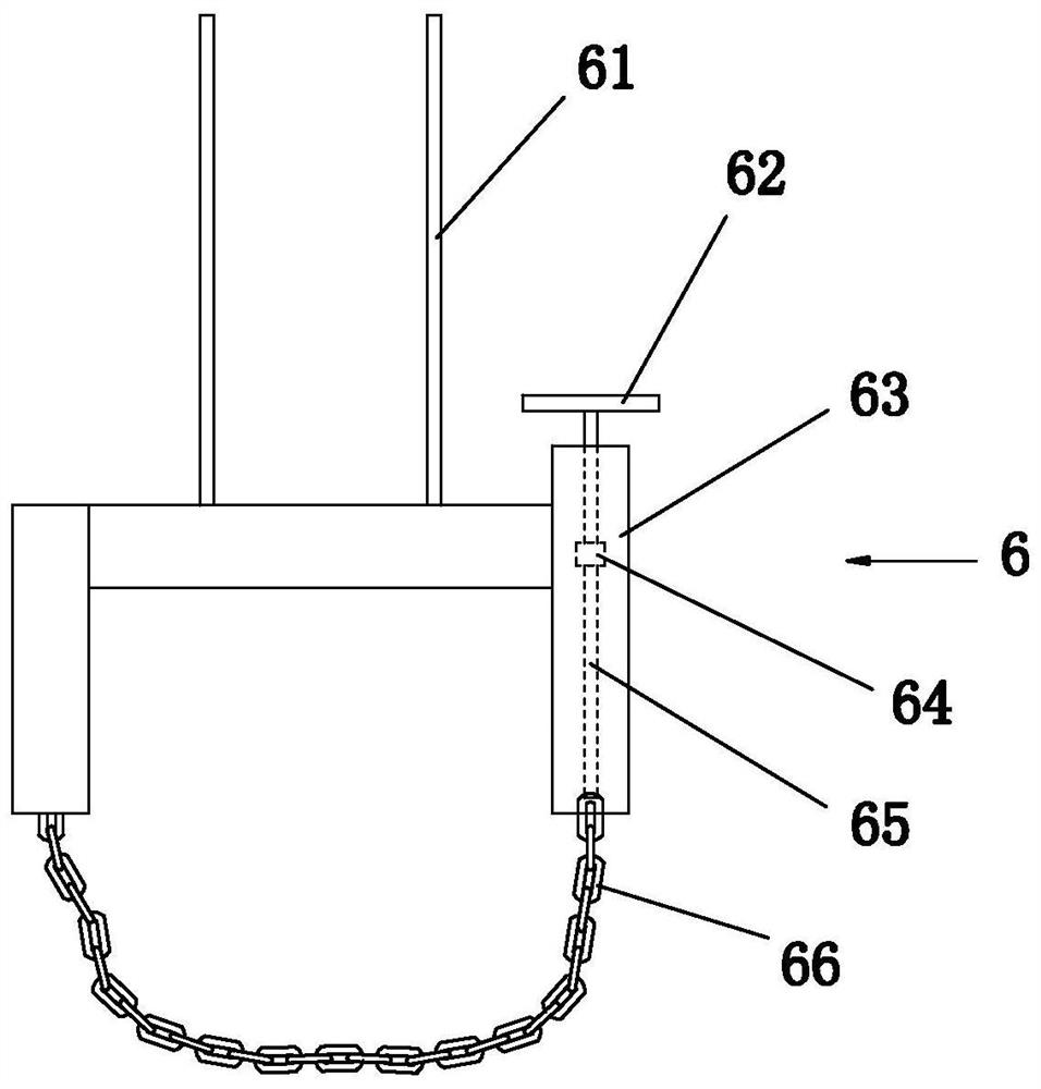
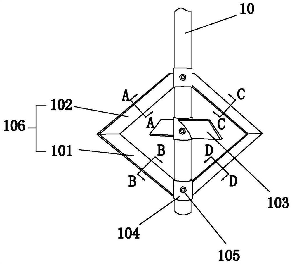
[0027] Such as figure 1 with figure 2 A high-efficiency mixer shown includes a mixer body, a mixing rod 10 and a motor 3. The mixer body includes a sealing cover 11, two electric telescopic rods 1, a fixed seat 8, a hydraulic telescopic rod 4, a mounting frame 2 and a fixed mixing barrel Frame 6.

[0028] The lower end of the fixing base 8 is a horizontal plate, and a fixing hole is opened on the horizontal plate, and the fixing hole is fixed on a horizontal installation surface by bolts. The hydraulic telescopic rod 4 is fixed on the fixed seat 8 vertically upwards. The hydraulic telescopic rod includes devices necessary for hydraulic control such as a hydraulic oil tank and an oil circuit. The hydraulic telescopic rod 4 drives the upper parts to move up and down to withstand greater force. Mounting frame 2 is horizontally fixed to the upper movable end of hydraulic telescopic rod 4, hydraulic telescopic rod 4 drives mounting frame 2 to move up and down, stirring rod 10 is inst...


PUM


Abstract

The invention discloses a high-efficiency mixer, which comprises a mixer body, a stirring rod and a motor. The stirring rod is vertically installed on the mixer body downwards. The lower end of the stirring is provided with at least two propeller blades and at least two angled blades, the angled blades include an upper stirring plate and a lower stirring plate, and the upper stirring plate and the lower stirring plate are respectively fixed on the outer wall of the stirring rod. The outer ends of the stirring plate and the lower stirring plate are connected to each other to form a knuckle, the propeller blade is used to press down the powdery material, and the knuckle blade is used to drive the slurry to rotate. The invention can stir materials better and faster.

Description

Technical field [0001] The invention relates to a high-efficiency mixer. Background technique [0002] Blenders are widely used in the pharmaceutical, food processing and chemical industries. The use of blenders for material processing can help improve work efficiency. Existing mixers can be divided into two types: drum type and shaft type. The drum type mixer realizes the mixing and mixing of materials through the rotation of the barrel. The barrel of the shaft type mixer is fixed, and the blade is driven by the stirring shaft to rotate. Stir and mix the materials. [0003] The blade structure of common mixers on the market is single, which cannot handle the mixing of powder and slurry well, and the efficiency is low; the material is completely exposed to the air during the mixing process, the slurry is easy to volatilize and produce organic gas, and powder is easy to occur Raising causes dust pollution and harms the staff; traditional mixers require manual control and work effi...

Claims


Application Information

Patent Timeline
Patent Type & Authority Patents(China)
IPC IPC(8): B01F7/16B01F7/22B01F7/32B01F15/00B01F7/00B01F27/91B01F27/96
CPCB01F27/074B01F27/192B01F27/805B01F27/91B01F27/96B01F35/00B01F2035/351B01F35/181
Inventor 许坚王凌
Owner GUANGZHOU RUXING TECH DEV
Why Eureka
Try Eureka