
Gas-liquid mechanical coupled agitator

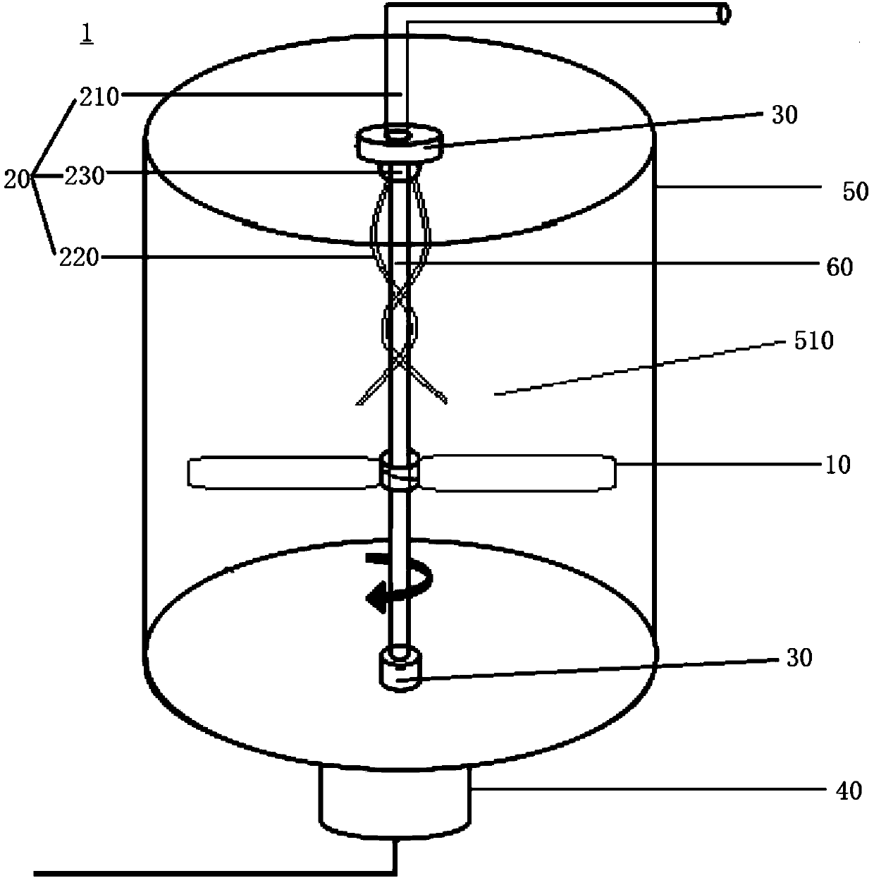
A stirring device and mechanical technology, which is applied to mixers, mixer accessories, mixers and other directions with a rotating stirring device, can solve the problems of low gas-liquid mixing efficiency, large electric energy demand, and many stirring dead zones, and reduce the stirring energy. consumption, improve the effect of mixing efficiency

Pending Publication Date: 2018-05-11
CHINA ENFI ENGINEERING CORPORATION
View PDF0 Cites 6 Cited by
  • Summary
  • Abstract
  • Description
  • Claims
  • Application Information

AI Technical Summary

Problems solved by technology

However, the stirring method of this device is still the traditional single mechanical stirring, which requires more electric energy than gas-liquid mechanical coupling stirring, has more dead zones in stirring, and lower gas-liquid mixing efficiency.

Method used


Image

  • Gas-liquid mechanical coupled agitator
  • Gas-liquid mechanical coupled agitator
  • Gas-liquid mechanical coupled agitator

Examples


example 1

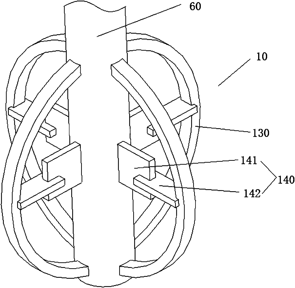
[0055] Such as figure 2 As shown, the stirring member 10 of this example includes a stirring rib 130 and a blade 140, the stirring rib 130 is arranged along the axial direction of the rotating shaft 60 and is arc-shaped, the two ends of the stirring rib 130 are connected on the rotating shaft 60, and the blade 140 includes a first One end of the first leaf 141 is connected with the rotating shaft 60 , one end of the second leaf 142 is connected with the first leaf 141 , and the other end of the second leaf 142 is connected with the stirring rib 130 . The thickness direction of the first leaf portion 141 is perpendicular to the thickness direction of the second leaf portion 142 .

example 2

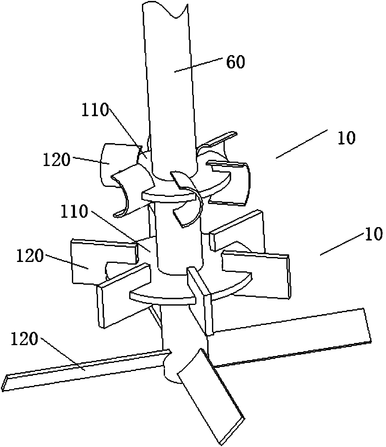
[0057] Such as image 3 As shown, there are a plurality of stirring elements 10 in this example, and the plurality of stirring elements 10 are arranged at intervals along the axial direction of the rotating shaft 60 . The stirring member 10 above includes a hub 110 and paddles 120 , the hub 110 is fixedly connected to the rotating shaft 60 , and the paddles 120 are connected to the hub 110 . The stirring member 10 at the bottom only includes the blade 140 , and the paddle 120 is directly connected to the rotating shaft 60 .

[0058] The application of the gas-liquid mechanical coupling stirring device 1 of this embodiment to achieve a uniform mixing effect is as follows:

[0059] Add 1000kg of mixing material fluid into the mixing tank 50, extend the nozzle of the air jet pipe 220 into the place 150mm below the liquid surface, the gas is sprayed into the mixing space 510 through the air guide pipe 210 and the air jet pipe 220, and at the same time, start the motor 40 to drive...


PUM


Abstract

The invention discloses a gas-liquid mechanical coupled agitator. The gas-liquid mechanical coupled agitator comprises an agitating cylinder, a rotating shaft, an agitating part and an air injection assembly; the agitating cylinder defines a stirring space, the rotating shaft is arranged in the stirring space, the agitating part is connected to the rotating shaft, the agitating part is used for stirring a fluid material put in the stirring space, and the air injection assembly is used for passing gas into the stirring space to stir the fluid material. According to the gas-liquid mechanical coupled agitator, by arranging the agitating part to stir the fluid material and the air injection assembly to pass gas into the stirring space to stir the fluid material, the effective combination of gas stirring and mechanical stirring can achieve the effect of chaotic stirring. In this way, it can solve the problem of excessive energy input in the process of mechanical stirring, and solve the problem of stirring blind areas in gas stirring, thus, the mixing efficiency in the stirring space is greatly improved, at the same time, the energy consumption of agitation is reduced.

Description

technical field [0001] The invention relates to the field of industrial production stirring equipment, in particular to a gas-liquid mechanical coupling stirring device. Background technique [0002] The mechanical stirring process is to use the rotation of the stirrer in the stirring tank to convert the mechanical energy of the stirring paddle into the kinetic energy of the fluid, so that the fluid can obtain a stable flow field, and transfer heat, mass and momentum while complex chemical reactions occur in the flow field , so as to achieve a thorough mixing process. The purpose of fluid mixing is to mix and couple a variety of fluids with each other, so the movement of the fluid during the mixing process is extremely complicated. Whether it is analyzing the performance of existing mixing equipment or designing new mixing equipment, it can be used as a reference basis only some experience Summarize. [0003] Gas agitation is a method of injecting air into a liquid to agit...

Claims


Application Information

Patent Timeline
Patent Type & Authority Applications(China)
IPC IPC(8): B01F13/02B01F7/20B01F15/00B01F33/40B01F27/906
CPCB01F27/074B01F27/112B01F27/19B01F27/906B01F33/405B01F33/402B01F33/4094B01F35/3204
Inventor 李鹏姚心郭天宇
Owner CHINA ENFI ENGINEERING CORPORATION
Learn More