Numerical control milling equipment

A technology of CNC milling and CNC milling machine, applied in milling machine equipment, metal processing equipment, milling machine and other directions, can solve the problems of difficult to achieve dimensional accuracy, inconsistent workpiece clamping force, high defect rate, improve processing efficiency and ensure consistent processing sexual effect

Pending Publication Date: 2018-05-11
THERMAL GROUP TECH HUIZHOU
View PDF10 Cites 2 Cited by
  • Summary
  • Abstract
  • Description
  • Claims
  • Application Information

AI Technical Summary

Problems solved by technology

The structure design of the existing milling machine equipment is simple. There are two traditional processing methods. One is milling on a CNC milling machine after a single product workpiece is fixed. After milling one surface, the other surface is milled. The dimensional accuracy can be guaranteed, but very low capacity
The second is that multiple product workpieces are clamped and clamped together on the same clamping surface, and the other surface is milled after milling one surface; the clamping force of the workpiece is inconsistent, which may easily cause the size to be out of tolerance; the production capacity has been improved, but the dimensional accuracy is not easy Achieved, high defect rate

Method used


Image

  • Numerical control milling equipment
  • Numerical control milling equipment
  • Numerical control milling equipment

Examples


Embodiment Construction

[0027] It should be understood that the specific embodiments described here are only used to explain the present invention, not to limit the present invention.

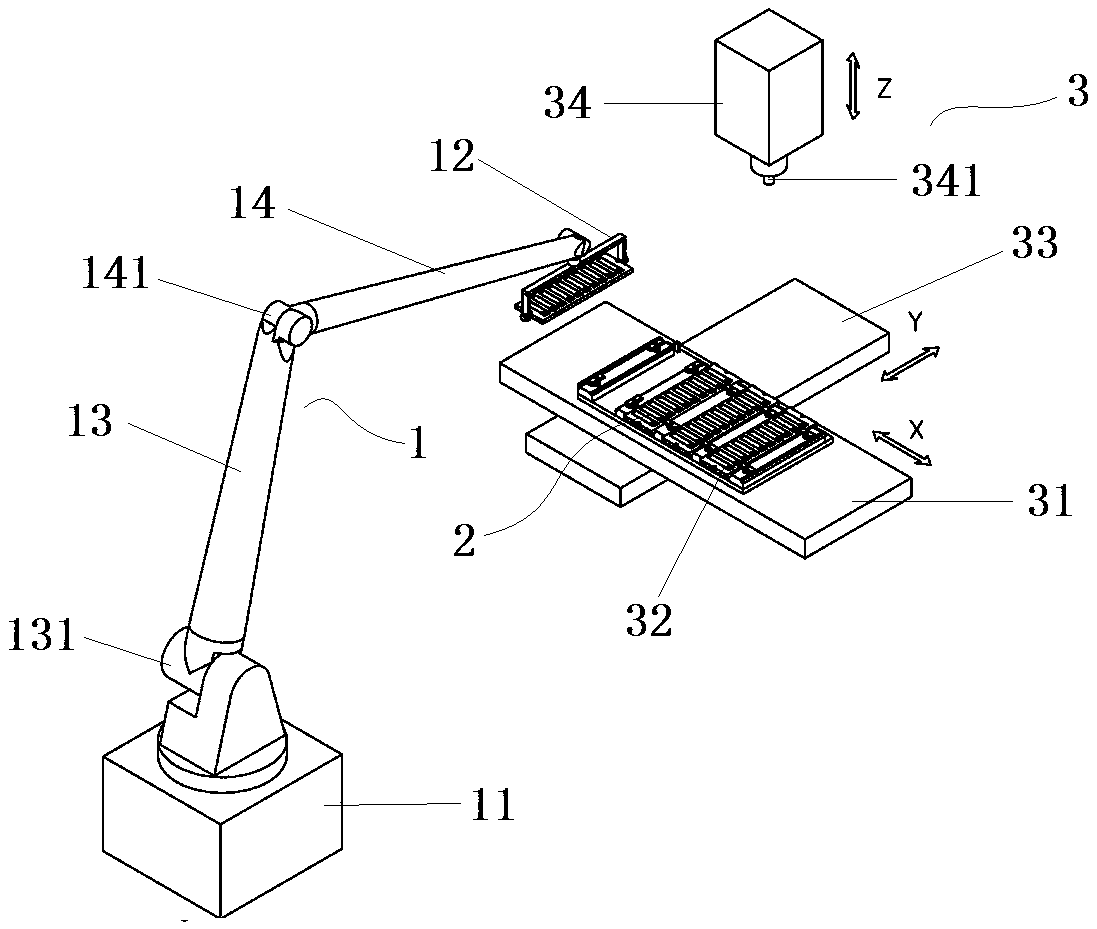
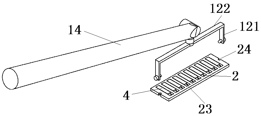
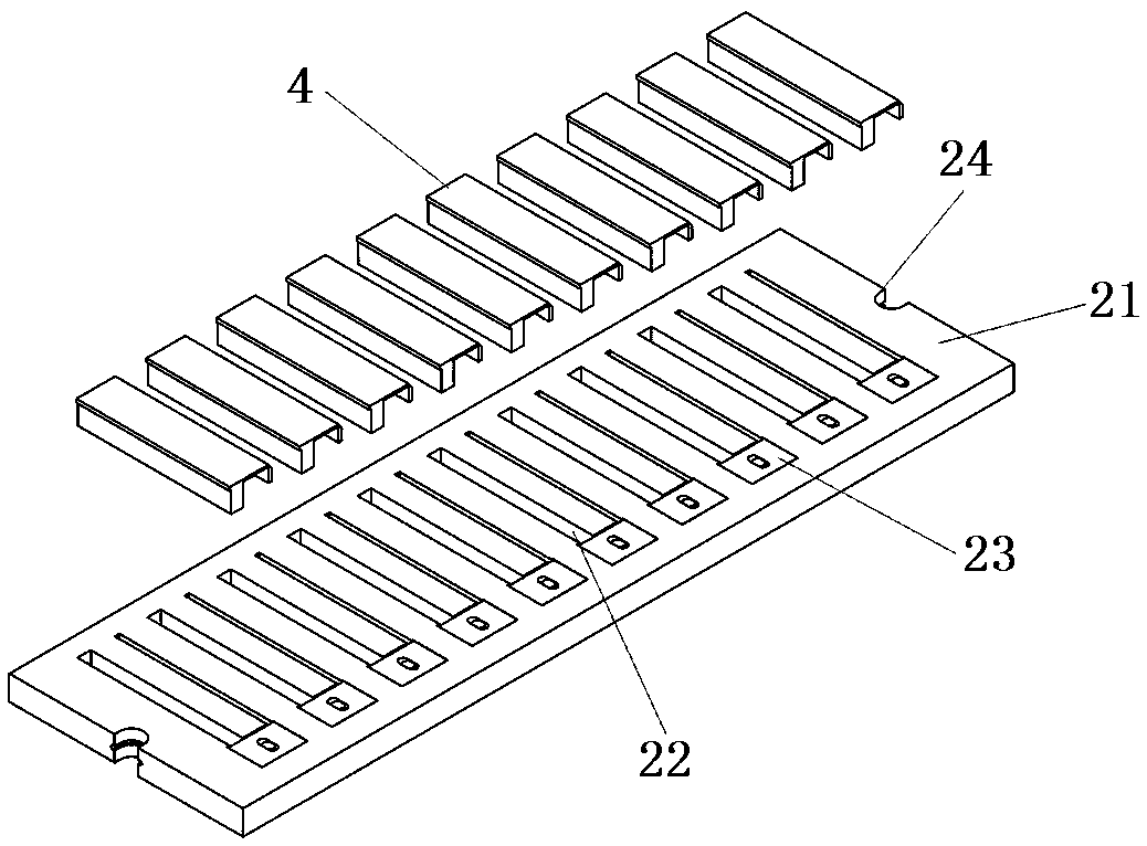
[0028] Such as figure 1 As shown, the present embodiment provides a kind of numerical control milling equipment, and this equipment comprises manipulator 1, turnover jig 2 and numerical control machine tool 3; The moving mechanism 33 and the Z-axis moving mechanism 34 are provided with a clamping fixture 32 for fixing the turnover fixture 2 on the X-axis moving mechanism; a milling cutter 341 for processing workpieces is provided on the Z-axis moving mechanism 34; A plurality of turnover jigs 2 are installed on the jig 311 . The turnover fixture 2 includes a base plate 21, the thickness of which is slightly smaller than the thickness of the workpiece 4, so that the two processed end faces of the workpiece 4 can be directly exposed on the two end faces of the base plate 21; the base plate 21 is provided with a plurali...


PUM


Abstract

The invention discloses numerical control milling equipment. The numerical control milling equipment comprises a mechanical arm, turnover jigs and a numerical control milling machine. The numerical control milling machine comprises an X-axis moving mechanism, a Y-axis moving mechanism and a Z-axis moving mechanism. The X-axis moving mechanism is provided with a clamping jig. The Z-axis moving mechanism is provided with a milling cutter. The clamping jig is provided with the multiple workpiece clamping turnover jigs. Each workpiece clamping turnover jig comprises a bottom plate, wherein the thickness of the bottom plate is slightly smaller than the thicknesses of workpieces, the bottom plate is provided with a plurality of workpiece clamping holes for storing the workpieces, one end of eachclamping hole is provided with a wedge-shaped block used for clamping the workpiece, the two sides of the bottom plate are provided with jig clamping grooves, and the mechanical arm moves and turns the turnover jig by clamping the jig clamping grooves. According to the numerical control milling equipment, fixation of the multiple workpieces is carried out through the turnover jigs, fixation of the multiple turnover jigs is achieved through clamping bases, moving and turning of the turnover jigs are achieved through cooperation of the mechanical arm and the turnover jigs, machining of two endfaces of each workpiece can be carried out, the machining efficiency of the milling machine is improved, and meanwhile the machining precision is guaranteed.

Description

technical field [0001] The invention relates to numerical control milling equipment, in particular to a numerical control milling equipment. Background technique [0002] CNC milling machine equipment refers to machine tools that mainly use milling cutters to process various surfaces on workpieces. The structure design of the existing milling machine equipment is simple. There are two traditional processing methods. One is milling on a CNC milling machine after a single product workpiece is fixed. After milling one surface, the other surface is milled. The dimensional accuracy can be guaranteed, but The production capacity is very low. The second is that multiple product workpieces are clamped and clamped together on the same clamping surface, and the other surface is milled after milling one surface; the clamping force of the workpiece is inconsistent, which may easily cause the size to be out of tolerance; the production capacity has been improved, but the dimensional acc...

Claims


Application Information

Patent Timeline
Patent Type & Authority Applications(China)
IPC IPC(8): B23C1/06B23Q7/04B23Q3/06
CPCB23C1/06B23Q3/061B23Q7/04
Inventor 邓中应姜文新谭弘平
Owner THERMAL GROUP TECH HUIZHOU
Why Eureka
Try Eureka