
Positioning device for flattening bottom face of cylinder body

A technology of positioning device and cylinder block, applied in the direction of positioning device, clamping, supporting, etc., can solve the problems of inaccurate positioning of the cylinder block and affect the processing efficiency, so as to improve the positioning accuracy and clamping stability, improve the processing efficiency, Action-reliable effects

Pending Publication Date: 2018-05-11
GUANGXI YUCHAI MASCH CO LTD
View PDF7 Cites 0 Cited by
  • Summary
  • Abstract
  • Description
  • Claims
  • Application Information

AI Technical Summary

Problems solved by technology

[0003] At present, there is a lack of a device that can locate the two spindle holes at the farthest end of the cylinder block and level the bottom surface of the cylinder block for effective clamping. There are problems that the positioning of the cylinder block is not accurate enough and affects the processing efficiency.

Method used


Image

  • Positioning device for flattening bottom face of cylinder body
  • Positioning device for flattening bottom face of cylinder body
  • Positioning device for flattening bottom face of cylinder body

Examples


Embodiment 1

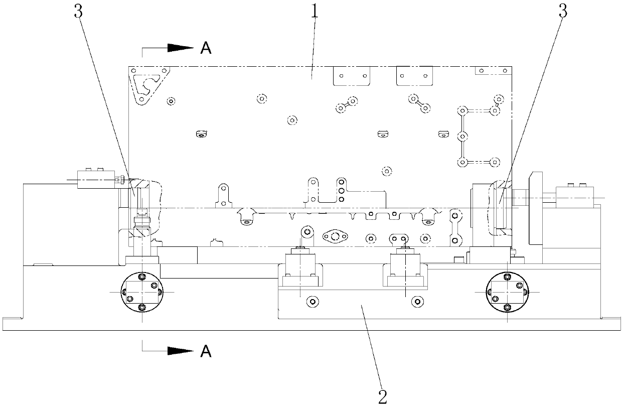
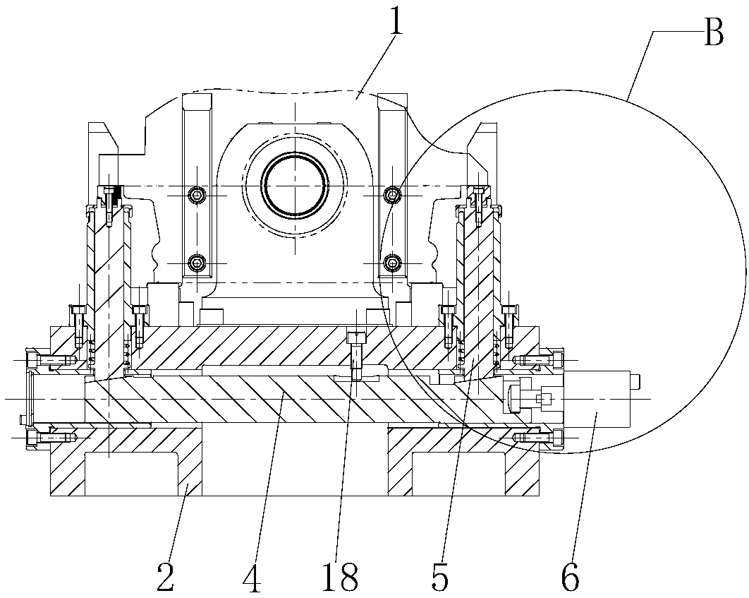
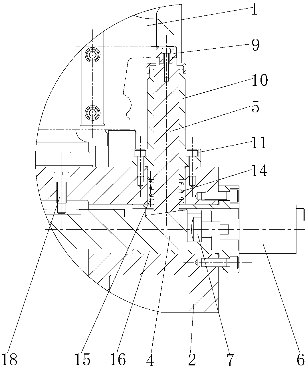
[0039] refer to Figure 1-4 , the two ends on the wedge iron 4 are respectively provided with wedge-shaped chute 13 with a positive inclination, correspondingly, the bottom of guide post 5 is provided with a connecting portion matching with wedge-shaped chute 13, and the inclination of wedge-shaped chute 13 The direction is consistent with the thrust direction of the driving device 6. When the driving device 6 drives the wedge iron 4 away from the driving device 6, the wedge-shaped chute 13 can push the two guide posts 5 to move upward at the same time until the two positioning blocks 9 and the cylinder block 1 The bottom surface is close until the cylinder block 1 is flattened and clamped. The present invention also includes a spring 14 sleeved on the lower part of the guide post 5. The lower part of the guide post 5 is provided with a limiting boss 15. One end of the spring 14 presses against the positioning guide sleeve 10 The lower end surface of the lower end, the other e...

Embodiment 2

[0051] refer to figure 1 , 7 -9, the two ends of the wedge iron 4 are respectively provided with reverse slope wedge-shaped dovetail grooves 12, correspondingly, the bottom of the guide post 5 is provided with a dovetail tenon matching the wedge-shaped dovetail groove 12, and the wedge-shaped dovetail groove 12 The inclination direction of the drive device 6 is opposite to the thrust direction of the drive device 6. When the drive device 6 drives the wedge iron 4 to approach the drive device 6, the wedge-shaped dovetail groove 12 can pull the two guide posts 5 to move upward at the same time until the two positioning blocks 9 and the cylinder block The bottom surface of 1 is close until the end is flat and clamped to the cylinder block 1. When the driving device 6 drives the wedge iron 4 away from the driving device 6, the wedge-shaped dovetail groove 12 can push the guide post 5 to move downward to realize the release of the cylinder block 1. The wedge-shaped dovetail groove...


PUM


Abstract

The invention discloses a positioning device for flattening the bottom face of a cylinder body. The positioning device comprises a pedestal used for supporting the cylinder body. Locating pins capableof stretching into spindle holes of the cylinder body are formed in the two ends of the pedestal correspondingly. A plurality of iron wedges capable of sliding transversely are arranged inside the pedestal. Guide pillars which are in contact connection with the iron wedges and can slide up and down to flatten the cylinder body are arranged inside the pedestal. A driving device used for driving the iron wedges to move is arranged at one side of the pedestal. Connecting bolts connected with the iron wedges are arranged at one end of the driving device. Correspondingly, the iron wedges are provided with clamping grooves matched with the head portions of the connecting bolts. According to the positioning device, the locating pins are used for positioning the cylinder body, the iron wedges arefurther used for pushing the two guide pillars to move upwards at the same time so as to flatten and clamp the cylinder body, the cylinder body can be accurately positioned and effectively clamped, and the machining quality stability can be improved.

Description

technical field [0001] The invention relates to the technical field of engine cylinder block processing, in particular to a positioning device for flattening the bottom surface of the cylinder block. Background technique [0002] The distance from the top surface of the engine cylinder block to the main shaft hole, the flatness of the top surface, the parallelism between the top surface and the main shaft hole, and the verticality between the cylinder hole and the main bearing hole all have high precision requirements. The processing of these key parts Accuracy will directly affect the performance and service life of the engine. In the fine milling top surface of the engine cylinder block and the fine boring cylinder hole processing process, in order to ensure the distance from the top surface to the main shaft hole, the flatness of the top surface, the parallelism between the top surface and the main shaft hole, and the perpendicularity between the cylinder hole and the mai...

Claims


Application Information

Patent Timeline
Patent Type & Authority Applications(China)
IPC IPC(8): B23Q3/06
CPCB23Q3/062
Inventor 冯文源
Owner GUANGXI YUCHAI MASCH CO LTD
Learn More