Single motor coupler only for electric vehicle

A pure electric vehicle, single-motor technology, applied in electric power units, power units, vehicle components, etc., can solve the problems of inability to differentiate between front and rear wheels, reduce battery life, occupy chassis space, etc., and achieve short gear switching intervals. , The effect of shortening the shift interval and improving work efficiency

Pending Publication Date: 2018-05-11
LIAOCHENG UNIV
View PDF2 Cites 3 Cited by
  • Summary
  • Abstract
  • Description
  • Claims
  • Application Information

AI Technical Summary

Problems solved by technology

The motor will generate strong electromagnetic interference during frequent and large-scale speed changes, which will have a bad impact on the motor and its controller
At the same time, if the output power of the battery pack changes too frequently, it is easy to cause uneven power of each battery unit inside the battery pack, thereby reducing the life of the battery pack.
The traditional transmission system uses the transmission shaft device, which occupies the chassis space, and at the same time reduces the transmission efficiency of the power transmission system, which affects fuel economy and power performance
[0003] As disclosed in CN201611044037, a dual-input and output power-free interrupt coupler adopts distributed drive, and the transmission system is complicated. After the motor passes through a series of transmission mechanisms, the output efficiency decreases, and the differential speed of the front and rear wheels cannot
[0004] Application No. 201710342894.6 discloses a single-motor hybrid drive system based on a power coupler, which is used for hybrid electric vehicles and uses three clutches and one brake. The gear shifting process requires the manipulation of clutches and brakes, and the operation is complicated. There is an obvious power interruption during the shifting process, resulting in power loss

Method used


Image

  • Single motor coupler only for electric vehicle
  • Single motor coupler only for electric vehicle
  • Single motor coupler only for electric vehicle

Examples


Embodiment Construction

[0029] The present invention will be further described below in conjunction with the accompanying drawings and embodiments.

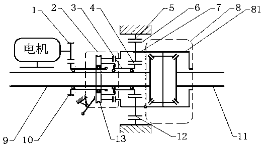
[0030] Such as figure 1 As shown, a single-motor coupler for pure electric vehicles includes: motor, sun gear 4, ring gear 5, planetary gears 6, 12, planetary carrier 7, hollow gear shaft 3, constant mesh gears 1, 10, gear position Switching mechanism 2, differential 8;

[0031] The motor is connected with the gear switching mechanism 2;

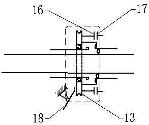
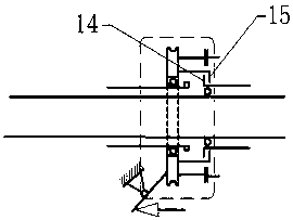
[0032] The gear switching mechanism is equipped with a pressure plate 14 and a pressure plate 16. When the gear switching mechanism 2 shifts gears, the shift lever 18 pushes the shift slider 13 under the push of an external force, so that the pressure plate 14 is separated from the driven plate 15. The pressure plate 16 is pressed and combined with the driven plate 17 to realize the switching of the gear position;

[0033] The driven disc 15 of the gear switching mechanism is connected with the sun gear 4;

[0034...


PUM


Abstract

The invention discloses a single motor coupler only for an electric vehicle. The single motor coupler is composed of a motor, a sun wheel, a ring gear, two planet gears, a planet carrier, a hollow gear shaft, two constant meshing gears, and a gear shifting mechanism, and a differential mechanism. The single motor coupler includes two drive gear positions including a drive gear position A and a drive gear position B; and the drive gear position A is a low gear to achieve a larger transmission ratio, and the drive gear position B is a high gear. The single motor coupler effectively shortens gear-shifting interval; the power layout of a traditional automobile is changed, the transmission system is simplified, and the transmission efficiency is improved; the structure is simple, the weight ofa vehicle body is reduced, and meanwhile, the remaining space of a chassis is increased; the two drive gear positions are realized, and the speed and power demands under different road conditions aresatisfied, so that the motor runs in a high efficiency range and the efficiency of the motor is improved; and the gear-shifting interval is short, energy loss is reduced, the energy utilization is improved, and the adverse effect of power interruption on driving is reduced.

Description

technical field [0001] The invention relates to a coupler for an electric vehicle, in particular to a single-motor coupler for a pure electric vehicle. technical background [0002] At present, almost all electric models are equipped with a single-speed transmission, and do not match a variable-speed transmission like a gasoline engine model. In urban road conditions, the electric motor directly drives the single-speed transmission, but in low-speed conditions, the output torque of the electric motor is unstable, and it will be more difficult when encountering road conditions with steep slopes. Therefore, a reasonable transmission ratio like a transmission is required to achieve a reasonable distribution of vehicles under different road conditions. The motor will generate strong electromagnetic interference during frequent and large-scale speed changes, which will have a bad effect on the motor and its controller. At the same time, if the output power of the battery pack c...

Claims


Application Information

Patent Timeline
Patent Type & Authority Applications(China)
IPC IPC(8): B60K1/00B60K17/08B60K20/02
CPCB60K1/00B60K17/08B60K20/02
Inventor 郭洪强刘祥运
Owner LIAOCHENG UNIV
Why Eureka
Try Eureka