

Compact type lifting device
A lifting device, a compact technology, applied in lighting devices, hoisting devices, lighting auxiliary devices, etc., can solve the problems of reducing the number of kinetic energy lamps, increasing the horizontal volume, increasing the spacing of kinetic energy lamps, etc., and achieving a retractable length. The effect of improving, large extension space, and large lifting stroke
- Summary
- Abstract
- Description
- Claims
- Application Information
AI Technical Summary
Problems solved by technology
Method used
Image

Examples
Embodiment 1
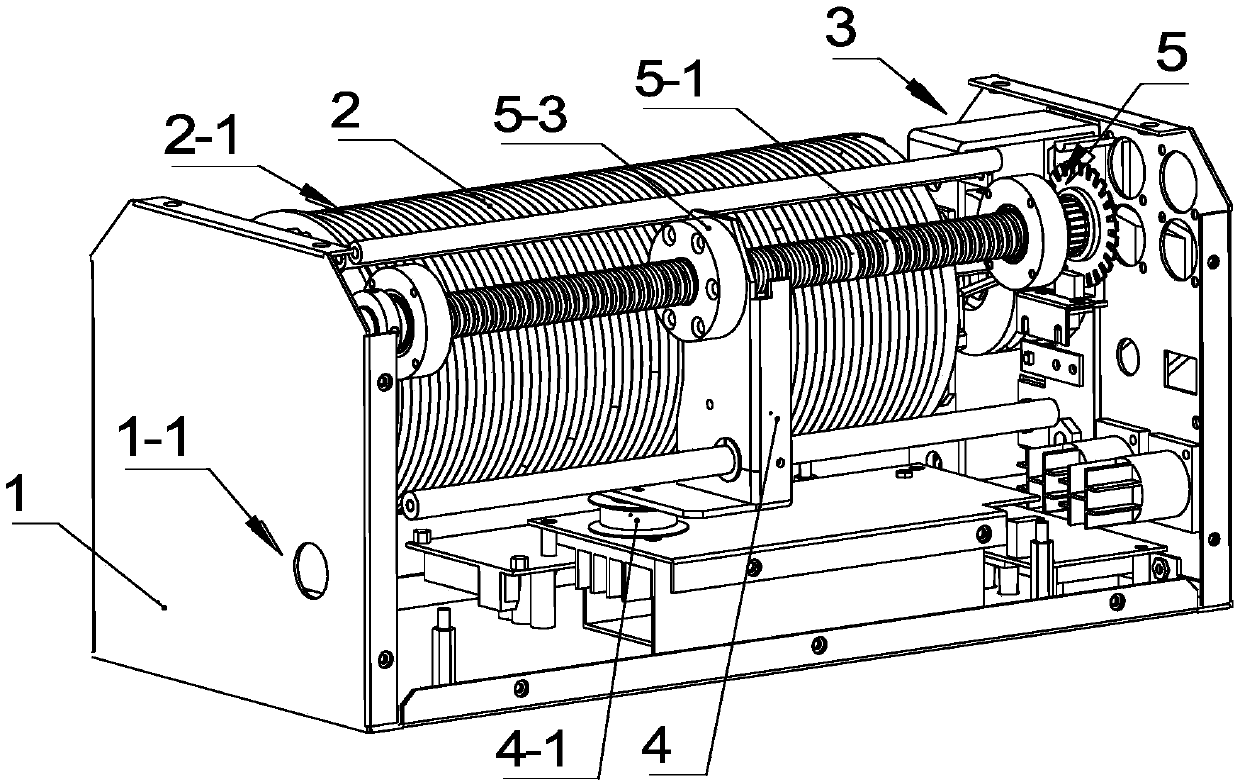
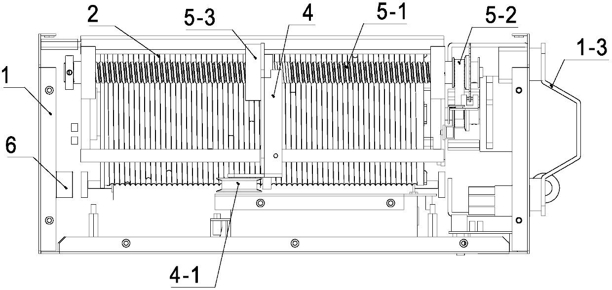
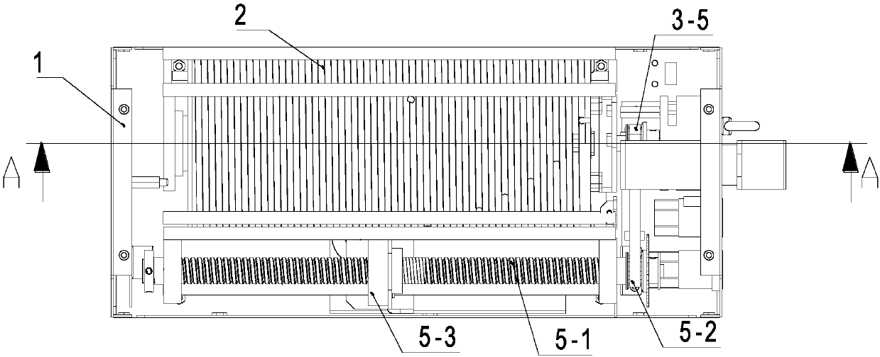
[0040] see figure 1 and Figure 6 , a compact lifting device of the present invention includes a box body 1, a winding actuator arranged in the box body 1, and a winding auxiliary mechanism that cooperates with the winding actuator to assist in winding the wires 1-2; Wherein, the box body 1 is provided with a wire inlet and outlet 1-1, and the rewinding actuator includes a rewinding drum 2 and a rotating drive mechanism 3 that drives the rewinding drum 2 to rotate the rewinding and unwinding wire; the rewinding auxiliary The mechanism is arranged on one side of the winding drum 2, including a moving frame 4 used to limit the position of the wires 1-2 being wound up in the axial direction of the winding drum 2 and used to drive the moving frame 4 in the axial direction of the winding drum. The mobile drive mechanism 5 that moves, the positioning part 4-1 for positioning the wire 1-2 is arranged on the moving frame 4, and the wire 1-2 is wound up after winding around the posit...
Embodiment 2
[0058]The difference between this embodiment and Embodiment 1 is that the mobile drive mechanism 5 is composed of a second motor and a screw rod 5-1 transmission mechanism, and is driven independently by the second motor, wherein the screw rod 5-1 transmission mechanism The screw mandrel 5-1 is arranged axially along the winding drum 2, the output shaft of the second motor is connected with the screw mandrel 5-1, and the screw nut in the transmission mechanism of the moving frame 4 and the screw mandrel 5-1 5-3 connection. During work, the second output shaft rotates to drive the screw mandrel 5-1 to rotate, and then drives the screw nut 5-3 and the mobile frame 4 connected to the screw nut 5-3 to move along the axial direction to perform the auxiliary task of winding.
[0059] Refer to Embodiment 1 for implementation of other implementation modes other than the above in this embodiment.
PUM
 Abstract
Description
Claims
Application Information