
Concrete vibrator capable of adjusting frequency

A vibrator and concrete technology, which is applied in construction, building structure, construction material processing, etc., can solve the problems of easy damage to the driving mechanism, difficulty in changing the speed for a long time, etc., and achieve the effect of improving the vibration effect

Active Publication Date: 2018-05-11
仪征市兴月混凝土有限公司
View PDF6 Cites 6 Cited by
  • Summary
  • Abstract
  • Description
  • Claims
  • Application Information

AI Technical Summary

Problems solved by technology

[0003] Considering that it is difficult for the ordinary power drive mechanism to change the speed for a long time, it is easy to damage the drive mechanism; therefore, the speed of the flexible shaft of the vibrator is basically stable, which makes the vibration frequency of the vibrator basically fixed, which is not conducive to outputting multiple frequencies on the concrete site. Vibration waves, so that various parts of the concrete site can be fully vibrated

Method used


Image

  • Concrete vibrator capable of adjusting frequency
  • Concrete vibrator capable of adjusting frequency
  • Concrete vibrator capable of adjusting frequency

Examples


Embodiment 1

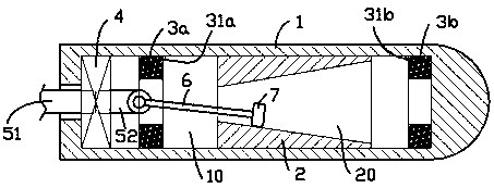
[0015] exist figure 1 In the first shown embodiment, the frequency-tunable concrete vibrator includes a rod-shaped base shell 1 made of non-ferromagnetic materials; an axial sliding cavity 10 is formed inside the base shell 1, and inside the sliding cavity 10 An iron slider 2 that can slide axially is matched, and a tapered cavity 20 is formed inside the slider 2, and the diameter of the front end of the tapered cavity 20 is larger than the diameter of the rear end; the two sides of the sliding area of ​​the slider 2 An electromagnet 3a, 3b is provided on each side; the electromagnet 3a, 3b is electrically connected to the control module (not shown) outside the base shell 1; the control module only makes one or zero at the same time The electromagnet is energized; the rear end inside the base shell 1 is provided with a coupling 4 for connecting the flexible shaft 51 outside the base shell 1 and the rotating shaft 52 inside the base shell, and the free end of the rotating shaft...

Embodiment 2

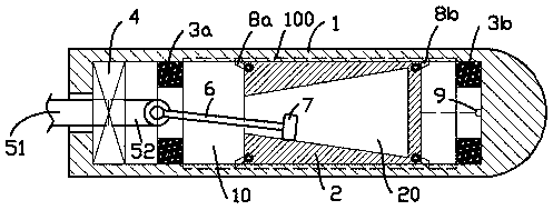
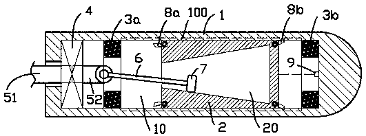
[0020] for figure 2 , image 3 The second embodiment shown is different from the first embodiment in that the end of the slider 2 has iron support blocks 8a, 8b connected by spring shafts. In a natural state, the iron support blocks 8a, 8b 8b leans outwards into the tooth groove 100 opened along the generatrix of the sliding chamber 10, so that the slider 2 is locked by the iron support blocks 8a, 8b and the tooth groove 100 and cannot be pushed into the iron support block. One end of the cog moves; figure 2 As shown, in the natural state, when the two electromagnets 3a, 3b are powered off, the iron support blocks 8a, 8b at both ends of the slider 2 are obliquely propped into the slots 100 opened along the generatrix of the sliding chamber 10 .

[0021] When the electromagnet is energized, the iron support block at the end close to the electromagnet on the slider 2 is drawn to the electromagnet under the action of magnetic attraction and deviates from the tooth groove 100,...


PUM


Abstract

The invention provides a concrete vibrator capable of adjusting a frequency. The concrete vibrator capable of adjusting the frequency comprises a clubbed base assembly made of nonferromagnetic materials; an axis direction sliding cavity is formed in the base assembly; the interior of the base assemble is matched with an iron sliding block which can slide in the axis direction; a conical cavity isformed in the sliding block; the diameter of the front end of the conical cavity is greater than the diameter of the rear end; two sides of a sidling area in the sliding block are separately providedwith electromagnets; the electromagnets are electrically connected with a control module outside the base assembly; one or none electromagnet is electrified at the same time by the control module; therear end of the base assembly is provide with a coupling to connect a flexible shaft outside the base assembly and a rotating shaft in the base assembly; a free end of the rotating shaft is connectedwith an oscillating bar in a pivot mode; and a free end of the oscillating bar stretches into the conical cavity, and is connected with a wobbler which can slide freely on the inner wall of the conical cavity in a coupling mode. During the working process, the vibrator can continuously adjust the vibration frequency to output more abundant vibration waves, and the vibrator is beneficial to improve the vibratory effect.

Description

technical field [0001] The invention relates to the field of building construction tools, in particular to a concrete vibrator. Background technique [0002] During the building construction process, the cast-in-place concrete needs to be vibrated to make the internal texture of the concrete uniform and eliminate internal air bubbles. The current concrete vibrator mainly includes a vibrating rod with an eccentric mechanism inside, and the eccentric mechanism is driven by a drive flexible shaft outside the vibrating rod; the current eccentric mechanism generally adopts a planetary mechanism, which includes a conical cavity, the free end of the rotating rod driven by a flexible shaft is connected with an eccentric rotating body that can rotate on the conical inner surface of the conical cavity, so that when the eccentric rotating body rotates rapidly in the conical cavity, that is Can produce higher vibration frequency. [0003] Considering that it is difficult for the ordin...

Claims


Application Information

Patent Timeline
Patent Type & Authority Applications(China)
IPC IPC(8): E04G21/08
CPCE04G21/08
Inventor 马人欢
Owner 仪征市兴月混凝土有限公司
Features
  • Generate Ideas
  • Intellectual Property
  • Life Sciences
  • Materials
  • Tech Scout
  • Unparalleled Data Quality
  • Higher Quality Content
  • 60% Fewer Hallucinations
Learn More