Wind-driven generator device

A technology for wind turbines and nacelles, applied in wind turbines, wind motor combinations, and wind turbines in the same direction as the wind. and other issues, to achieve good use value, maximize wind energy utilization, and generate large amounts of power

Pending Publication Date: 2018-05-11
无锡市天运五金机电有限公司
View PDF4 Cites 1 Cited by
  • Summary
  • Abstract
  • Description
  • Claims
  • Application Information

AI Technical Summary

Problems solved by technology

[0002] At present, with the rapid growth of the world's population, the power consumption is also increasing. Electricity is indispensable to human beings. In the recent stage, high-speed wind power generators make the internal coils generate current by short-circuiting their internal coils. , so as to reduce the speed of the windmill, so that the utilization rate of wind energy is low, and the power generation is small, so the purpose of efficient use of wind resources cannot be achieved. Because the internal coil current of the wind turbine increases to generate heat, if the wind speed continues to be large, it will cause wind turbines. The heat gathers and damages the wind power generator. As my country pays more and more attention to new energy in recent years, many policies issued are vigorously supporting the development and reuse of new energy. The process of pollution requires higher-end technology, so wind turbines have become an indispensable generator in the field of new energy
[0003] The currently used wind power generator device has complex structure, small power generation, high production cost, complex structure, large wind resistance, high material cost, not easy to process, can not make full use of wind resources for power conversion, and the utilization rate of wind energy Low, unable to meet the electricity consumption of household users, which has affected people's electricity consumption

Method used


Image

  • Wind-driven generator device
  • Wind-driven generator device
  • Wind-driven generator device

Examples


Embodiment Construction

[0018] The technical solutions in the embodiments of the present invention will be clearly and completely described below in conjunction with the accompanying drawings in the embodiments of the present invention. Obviously, the described embodiments are only some of the embodiments of the present invention, not all of them. Based on The embodiments of the present invention and all other embodiments obtained by persons of ordinary skill in the art without making creative efforts belong to the protection scope of the present invention.

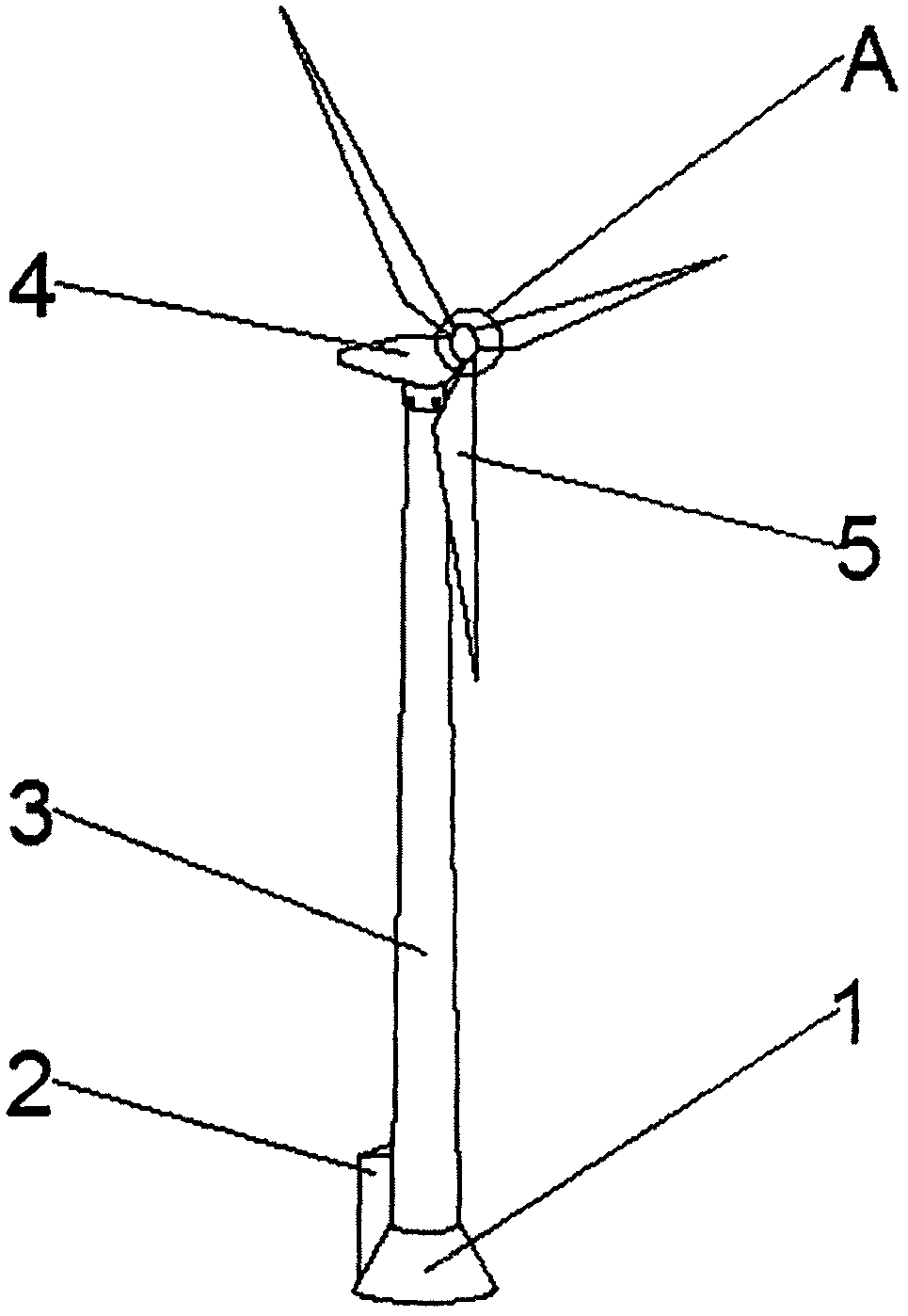
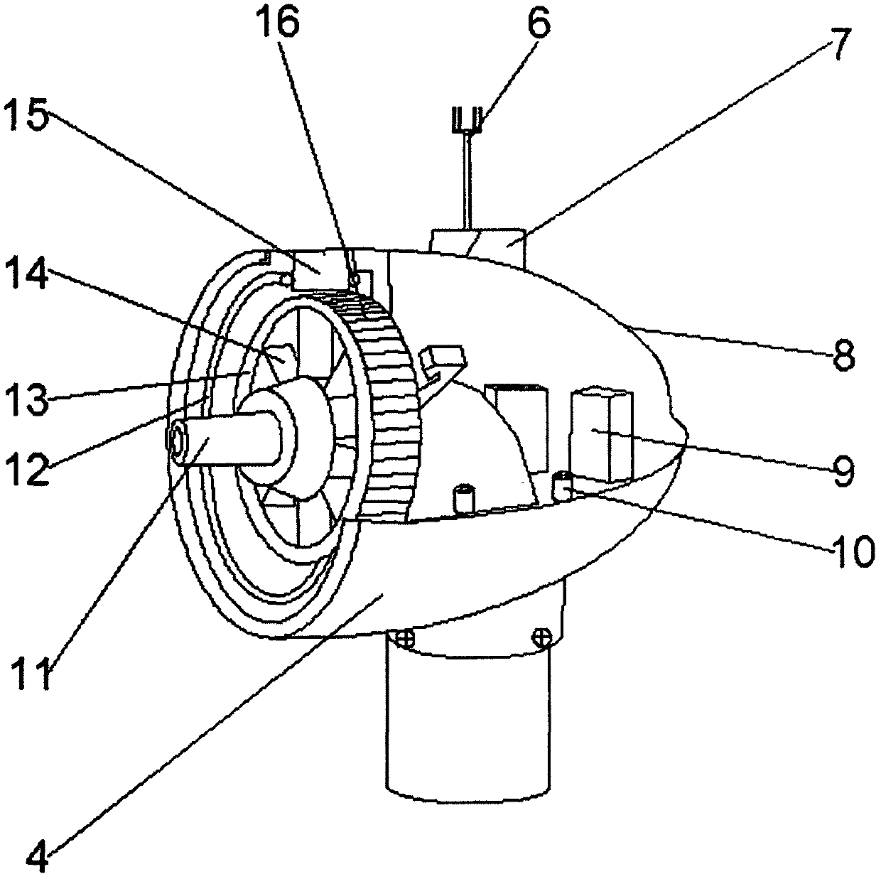
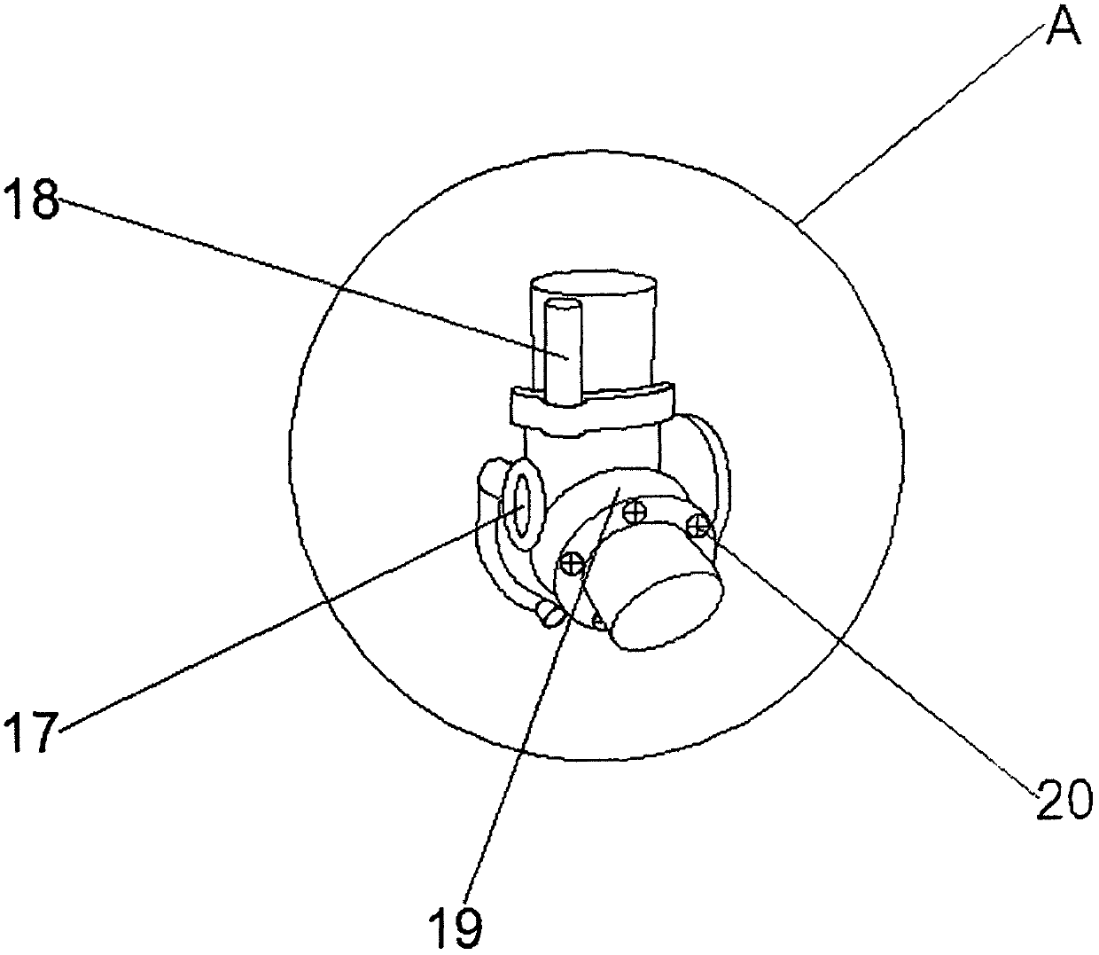
[0019] see Figure 1-3 , the present invention provides a technical solution: a wind power generator device, including a base 1, a tower rod 3, a cabinet 4 and a rotating blade 5, the upper part of the base 1 is fixedly connected with a tower rod 3, and the tower The rod 3 extends to the end and is movably connected to the cabin 4, the upper top of the cabin 4 is fixedly connected with a fixed base 7, the lower part of the fixed base 7 is fixedl...


PUM


Abstract

Disclosed is a wind-driven generator device. The wind-driven generator device comprises a pedestal, a machine cabinet, a tower pole and rotating blades. The tower pole is fixedly connected with the top of the pedestal, extends to the tail end and is movably connected with the machine cabinet. The rotating blades are movably connected with one side of the machine cabinet, and a fixing base is fixedly connected with the upper portion of the machine cabinet. The upper portion of the fixing base is fixedly connected with an anemometer, and the lower portion of the fixing base is fixedly connectedwith a machine cabin shell. A control cabinet is fixedly connected with one side of the interior of the machine cabin shell. According to the wind-driven generator device, the wind speed is measured through the anemometer, then the wind speed in the device is converted into electricity to be transmitted, the wind direction source is controlled through the control cabinet, and the direction of thewind-driven generator blades can be rapidly and accurately changed. The wind-driven generator device is reasonable in design, simple in structure, low in material cost and easy to process, can make full use of wind power resources to conduct conversion of the electricity, is high in utilization ratio of wind energy and high in generated energy, and has the high application value.

Description

technical field [0001] The invention relates to the technical field of generators, in particular to a wind power generator device. Background technique [0002] At present, with the rapid growth of the world's population, the power consumption is also increasing. Electricity is indispensable to human beings. In the recent stage, high-speed wind power generators make the internal coils generate current by short-circuiting their internal coils. , so as to reduce the speed of the windmill, so that the utilization rate of wind energy is low, and the power generation is small, so the purpose of efficient use of wind resources cannot be achieved. Because the internal coil current of the wind turbine increases to generate heat, if the wind speed continues to be large, it will cause wind turbines. The heat gathers and damages the wind power generator. As my country pays more and more attention to new energy in recent years, many policies issued are vigorously supporting the developmen...

Claims


Application Information

Patent Timeline
Patent Type & Authority Applications(China)
IPC IPC(8): F03D9/25F03D7/02F03D1/06F03D13/20F03D80/00
CPCF03D1/0658F03D7/0204F03D9/25F03D13/22F03D80/00F05B2270/602F05B2270/321F05B2260/301Y02E10/728Y02E10/72Y02P70/50
Inventor 席惠江
Owner 无锡市天运五金机电有限公司
Why Eureka
Try Eureka