Supercharge Your Innovation With Domain-Expert AI Agents!

Separating device used for inserts in die casting

A technology for separating devices and inserts, which is applied in the field of die-casting equipment, can solve the problems of high labor force and low collection efficiency of inserts, and achieve the effects of reducing labor intensity, reducing production costs, and improving collection efficiency

Active Publication Date: 2018-05-15
TONGLING ANDONG CAST STEEL
View PDF5 Cites 0 Cited by
  • Summary
  • Abstract
  • Description
  • Claims
  • Application Information

AI Technical Summary

Problems solved by technology

However, in the traditional production process, people take out the inlays manually, and finally arrange the inlays manually, which is labor intensive and the collection efficiency of the inlays is low

Method used


Image

  • Separating device used for inserts in die casting
  • Separating device used for inserts in die casting
  • Separating device used for inserts in die casting

Examples


Embodiment 1

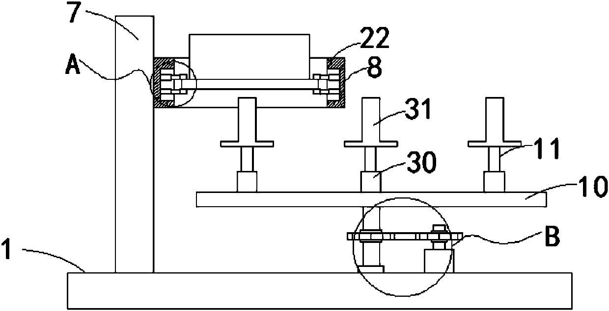
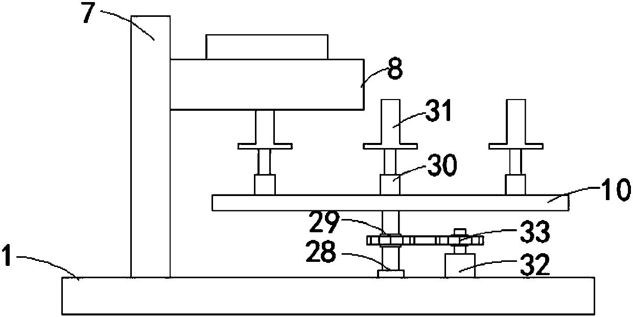
[0022] Embodiment 1: as Figure 1-4 As shown, a separation device for inserts in die-casting includes a base 1 on which a vertical rod 7 is arranged, and the vertical rod 7 and the die-casting mold 2 are respectively arranged on the base 1 at the left and right ends of the first rotating rod 3, The side wall of the vertical bar 7 is provided with a separation mechanism 8, the separation mechanism 8 is arranged on the end of the vertical bar 7 away from the first rotating rod 3, the upper end of the base 1 is rotatably connected with a support mechanism 9, and the support mechanism 9 is provided with a rotating disk 10, and the rotating disk 10 is located directly below the separation mechanism 8, and the rotating disk 10 is provided with a plurality of collecting devices 11, and the upper end of the base 1 is provided with a second rotating device 12, and the second rotating device 12 is located under the rotating disk 10 , the second rotating device 12 is in driving connectio...

Embodiment 2

[0026] Embodiment 2: as Figure 3-6 , applying the present invention to a cycle loading and unloading device for inserts in die-casting, comprising a base 1, the upper end of the base 1 is provided with a die-casting mold 2, and the upper end of the base 1 is rotatably connected with a first rotating rod 3, and on the first rotating rod 3 The first chain plate 4 is sleeved, and the side wall of the first rotating rod 3 is provided with a control mechanism 5, and the control mechanism 5 is located above the first chain plate 4, and the lower end of the control mechanism 5 is slidably connected with a clamping mechanism 16, The base 1 is provided with a first rotating device 6, and the first rotating device 6 is in transmission connection with the first chain plate 4, and the base 1 is provided with a vertical rod 7, and the vertical rod 7 and the die-casting mold 2 are respectively arranged on the first rotating rod On the base 1 at the left and right ends of 3, a separation me...


PUM


Abstract

The invention belongs to the technical field of die casting equipment, and particularly relates to a separating device used for inserts in die casting. The separating device comprises a pedestal. Thepedestal is provided with a vertical rod, and the vertical rod and a die-casting die are arranged on the pedestal and further located at the left end and the right end of a first rotating rod correspondingly. A separating mechanism is arranged on the side wall of the vertical rod and further located at the end, far away from the first rotating rod, of the vertical rod. The upper end of the pedestal is connected with a supporting mechanism in a rotating mode, and the supporting mechanism is provided with a rotary disk. The separating device used for the inserts in die casting has the advantagesthat ejection rods are used for ejecting die-casting workpieces, die-casting fittings can be separated from the inserts, the inserts are arranged on the ejection rods in a sleeving mode after the die-cast workpieces are separated by the separating mechanism, the inserts can be effectively arrayed and collected through the ejection rods, and therefore the collection efficiency of the inserts is effectively improved, the production cost of enterprises is reduced and the labor intensity of workers can be effectively relieved.

Description

technical field [0001] The invention belongs to the technical field of die-casting equipment, and in particular relates to a separation device for inserts in die-casting. Background technique [0002] Die casting (English: die casting) is a metal casting process, which is characterized by using the inner cavity of the mold to apply high pressure to the molten metal. Molds are usually machined from stronger alloys, a process somewhat similar to injection molding. Most die castings are ferrous, such as zinc, copper, aluminum, magnesium, lead, tin, and lead-tin alloys and their alloys. Depending on the type of die casting, a cold chamber die casting machine or a hot chamber die casting machine is used. [0003] The cost of casting equipment and molds is high, so the die casting process is generally only used for mass production of a large number of products. Manufacturing die-cast parts is relatively easy, generally requiring only four major steps with low incremental cost p...

Claims


Application Information

Patent Timeline
IPC IPC(8): B22D17/22
CPCB22D17/2236
Inventor 梅百荣徐志勇
Owner TONGLING ANDONG CAST STEEL
Features
  • R&D
  • Intellectual Property
  • Life Sciences
  • Materials
  • Tech Scout
  • Unparalleled Data Quality
  • Higher Quality Content
  • 60% Fewer Hallucinations
Learn More