Upsetting force self-compensation stirring tool for aclinal frication stir welding and welding method

A technology of friction stir welding and stirring tools, applied in welding equipment, manufacturing tools, non-electric welding equipment, etc., can solve the problems of weak upsetting force, achieve less flash, eliminate hole defects, and have strong implementability

Active Publication Date: 2018-05-15
SHANGHAI AEROSPACE EQUIP MFG GENERAL FACTORY
View PDF8 Cites 11 Cited by
  • Summary
  • Abstract
  • Description
  • Claims
  • Application Information

AI Technical Summary

Problems solved by technology

[0004] Aiming at the problem of weak upsetting force in the welding process of non-inclination friction stir welding, the present invention proposes an upsetting force self-compensating stirring tool suitable for non-inclination friction stir welding

Method used


Image

  • Upsetting force self-compensation stirring tool for aclinal frication stir welding and welding method
  • Upsetting force self-compensation stirring tool for aclinal frication stir welding and welding method
  • Upsetting force self-compensation stirring tool for aclinal frication stir welding and welding method

Examples


Embodiment 1

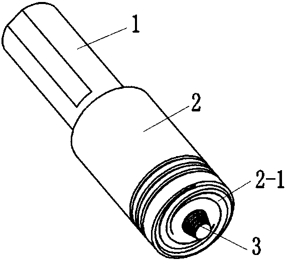
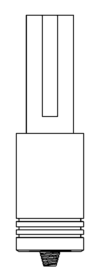
[0034] combine figure 1 , 2 Describe the implementation mode, an upsetting force self-compensating stirring tool suitable for friction stir welding without inclination, including a clamping section 1, a cylindrical section 2 and a stirring pin 3, the three parts are integrated from top to bottom, and the material of the stirring tool is High speed tool steel. The clamping section 1 is a cylinder with a diameter of 20mm, and the side of the cylinder is milled with planes for fastening. Cylindrical section 2 is a cylinder with a diameter of 24mm. There are 3 circles of cooling grooves on the side. The outer ring of the shaft shoulder is flat and has 2 clockwise Archimedes spiral grooves. is 7°, the groove depth is 0.05~0.2mm, the outer ring of the shaft shoulder and the cylindrical section are provided with a chamfer of 0.5mm, the diameter of the inner ring of the shaft shoulder is 16mm and is concave, the concave angle is 7°, and the inner ring of the shaft shoulder The inne...

Embodiment 2

[0036] A welding method of upsetting force self-compensating stirring tool suitable for non-inclination friction stir welding, adopting the stirring tool as described in embodiment 1, clamping and fixing the 5mm thick aluminum alloy to be welded on the welding platform, using fastening The screw fixes the stirring tool on the friction stir welding equipment. The inclination angle of the main shaft of the equipment is set to 0°, the rotation direction of the main shaft is set to counterclockwise, and the speed of 800rpm is used to penetrate the material to be welded at a penetration speed of 3mm / min. 0.1mm, welding at a welding speed of 300mm / min, after the welding is completed, the stirring tool is pulled out, and the welding is completed.


PUM


Abstract

The invention relates to an upsetting force self-compensation stirring tool suitable for aclinal frication stir welding. The upsetting force self-compensation stirring tool comprises a clamping section, a cylindrical section and a stirring needle. The clamping section, the cylindrical section and the stirring needle are of an integrated structure from top to bottom. The clamping section is a cylinder, and a plane used for fastening is milled in the side face of the clamping section. The cylindrical section is a cylinder, the diameter of the cylindrical section is larger than that of the clamping section, and a heat radiating groove is formed in the circumferential direction of the cylindrical section. The lower end face of the cylindrical section is a shaft shoulder. The outer circle of the shaft shoulder is a plane and is provided with at least two archimedes screw grooves. The inner circle of the shaft shoulder is inwards concave. The inwards-concave part and the stirring needle achieve smooth transition. The stirring needle is a thick-end-up circular truncated cone. The side face of the stirring needle has a thread feature. The upsetting force self-compensation stirring tool anda conventional inwards-concave type stirring tool have a function that upsetting force self-compensation is generated for welded material along with welding, and the hole defect liable to occur to aclinal frication stir welding can be avoided effectively.

Description

technical field [0001] The invention belongs to the field of welding, and relates to an upsetting force self-compensating stirring tool suitable for non-inclination friction stir welding and a welding method. Background technique [0002] Friction stir welding is a new type of solid-phase joining technology. Its principle is that the material to be welded is formed by the plastic flow of the high-speed rotating friction heat of the stirring head and the axial extrusion, and the butt surface is broken. solid phase connection. [0003] Compared with the traditional fusion welding method, friction stir welding has the characteristics of heat input, small welding deformation and excellent mechanical properties. It has been widely used in the welding of low melting point materials, such as aluminum and magnesium alloys. However, the traditional friction stir welding will cause the weld area to be thinner by 0.2~0.5mm than the base metal during the welding process, while the n...

Claims


Application Information

Patent Timeline
Patent Type & Authority Applications(China)
IPC IPC(8): B23K20/12B23K20/26
CPCB23K20/12B23K20/26
Inventor 王志国窦超江琛封小松黄征崔凡尹玉环徐奎
Owner SHANGHAI AEROSPACE EQUIP MFG GENERAL FACTORY
Why Eureka
Try Eureka