
Push-type clamping table

A clamping table, push-type technology, applied in the direction of workbench, manufacturing tools, etc., can solve the problems of incomplete clamping mechanism, reduced structure space, etc., and achieve the effect of fast action, reduced structure, and small action range

Pending Publication Date: 2018-05-15
JINHUA YAHU TOOLS
View PDF10 Cites 2 Cited by
  • Summary
  • Abstract
  • Description
  • Claims
  • Application Information

AI Technical Summary

Problems solved by technology

[0004] The present invention mainly aims at the shortcomings of the imperfect clamping mechanism, and invents a push-type clamping table, which adopts a faster, more accurate and stable propulsion structure, simplifies the number of connecting rods, reduces the structural space, controls the range of motion, and realizes fast and precise propulsion , while maintaining a high degree of stability

Method used


Image

  • Push-type clamping table
  • Push-type clamping table
  • Push-type clamping table

Examples


Embodiment 1

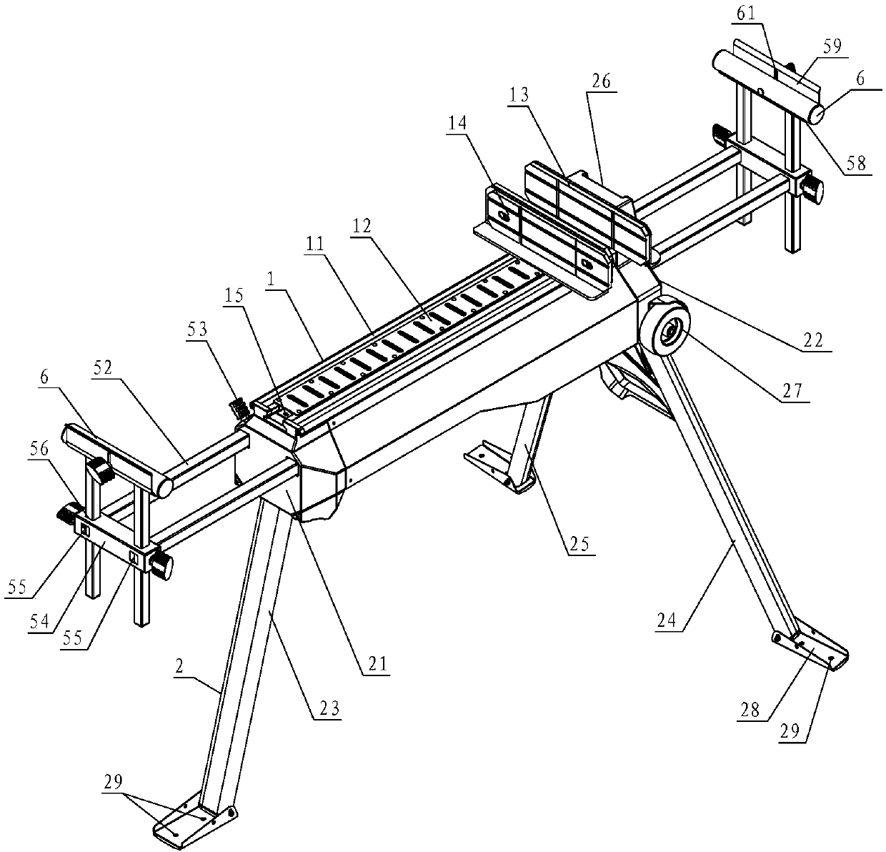
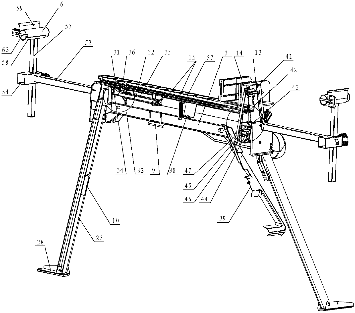
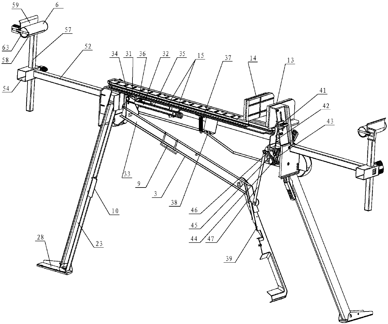
[0041] Such as figure 1 , 2 , 3, a push-type clamping table, including a table assembly 1, a tripod assembly 2 for support, a driving device 3 for driving the translation of the table, and a switch device 4 for locking the driving device.

[0042] The table assembly consists of a table base 11 , a table slide 12 , a static splint 13 and a dynamic splint 14 .

[0043] Wherein, the table base 11 is a strip-shaped profile, and there is a groove track in the center of the profile. From the cross section of the table base 11, the groove is an upper opening, and the groove is narrow at the top and wide at the bottom. An inverted T shape, or an inverted isosceles trapezoid combined with a square, etc.; one end of the table base 11 is provided with a static splint 13 .

[0044] The table slide 12 is a slat-shaped profile, the upper layer is a straight slat, and the lower part of the slat is set as a downward raised part, and the structure of the raised part is matched with the groov...

Embodiment 2

[0064] Such as Figure 7 As shown, compared with Embodiment 1, the difference of this embodiment is that there are no extension tubes, roller brackets and rollers at both ends of the table, and the clamping table is only used as a clamping table without the function of a miter saw support.


PUM


Abstract

The invention relates to a push-type clamping table. The push-type clamping table comprises a table top assembly and a foot stand assembly. The push-type clamping table is characterized in that the table top assembly comprises a table top pedestal, a table top sliding base, a static board clamping part and a dynamic board clamping part; a plurality of push through holes which are arrayed at intervals are formed in the board surface of the table top sliding base; a first foot stand supporting piece is arranged at one end of the table top pedestal, and a second foot stand supporting piece is arranged at the other end of the table top pedestal; and a driving device used for pushing the table top sliding base to move and a switching device capable of locking the driving device are arranged below the table top sliding base. According to the main defect that a clamping mechanism is not perfect, a faster and more accurate and stable pushing structure is adopted, the number of connecting rodsis decreased, the structure space is reduced, the movement range is controlled, fast and accurate pushing is achieved and meanwhile high stability can be maintained.

Description

technical field [0001] The invention relates to a woodworking clamping platform, in particular to a push-type clamping platform. Background technique [0002] During woodworking, it is usually necessary to clamp and fix the wood to be processed. Common clamping devices include slat type clamping table, flat type clamping table, and horse stool type clamping table. Among them, the strip-type clamping table has a relatively simple structure, which is mainly composed of parallel strips combined with screw fasteners. Generally, it can only clamp smaller-sized workpieces. The advantage is in terms of operation; the flat-type clamping table combines the clamping function. And the function of the workbench, the table is composed of two flat plates, the clamping function is realized through the relative displacement of the two plates, and the clamping range has been expanded, but it still cannot meet the clamping requirements of large-sized workpieces; The slatted table top is com...

Claims


Application Information

Patent Timeline
Patent Type & Authority Applications(China)
IPC IPC(8): B25H1/08
CPCB25H1/08
Inventor 盛晶何占丰王荣民李宝荆彦鹏黄永平李成华潘鹏
Owner JINHUA YAHU TOOLS
Learn More