
Glass lens bonding machine and glass lens automatic bonding method

A glass lens and laminating machine technology, which is applied in the direction of material gluing, mechanical equipment, connecting components, etc., can solve the problems that the parallelism of product A101 and product B102 cannot be guaranteed.

Active Publication Date: 2020-09-15
SUZHOU MAKING INTELLIGENT EQUIP CO LTD
View PDF6 Cites 0 Cited by
  • Summary
  • Abstract
  • Description
  • Claims
  • Application Information

AI Technical Summary

Problems solved by technology

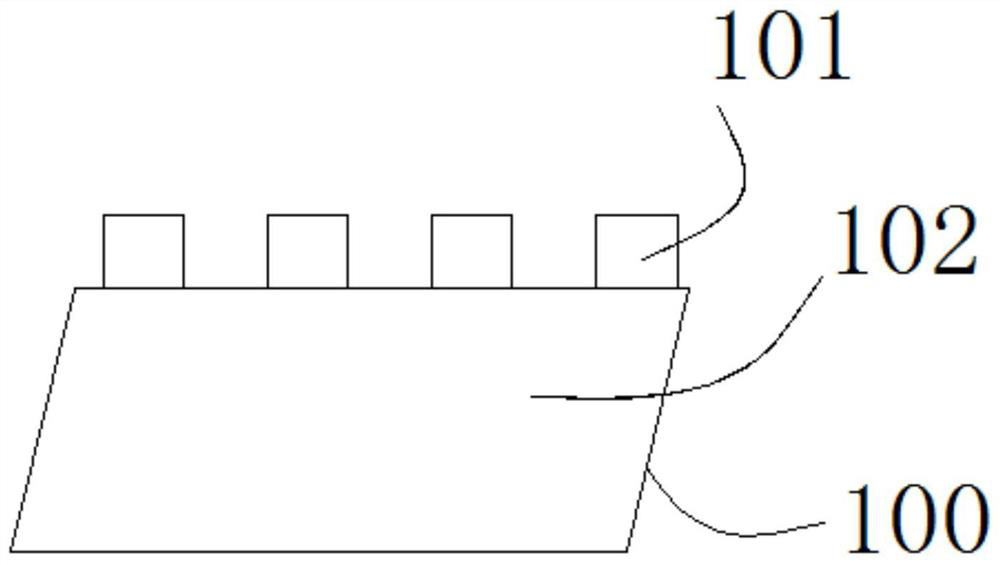
[0003] like figure 1 The assembly 100 shown includes product A 101 and product B 102 which are made of glass lenses and are attached to each other. Both product A 101 and product B 102 are made of glass; the current assembly method cannot guarantee that product A101 and product B 102 The parallelism between product B 102, and in the field of optics, the use of this product needs to ensure the parallelism between the two; therefore, it is necessary to provide a glass lens bonding machine and a glass lens automatic bonding method to solve the problem. above question

Method used


Image

  • Glass lens bonding machine and glass lens automatic bonding method
  • Glass lens bonding machine and glass lens automatic bonding method
  • Glass lens bonding machine and glass lens automatic bonding method

Examples


Embodiment

[0037] In the optical field, when the two lenses are in a state of extremely high parallelism, after the two lenses are bonded, an optical interference ring will be generated when the light is irradiated. Applying this principle, the glass lens can be bonded with a high pass rate;

[0038] see Figure 2 to Figure 5 , this embodiment shows a method for automatic bonding of glass lenses:

[0039] It uses a glass lens automatic laminating machine for automatic lamination of glass lenses;

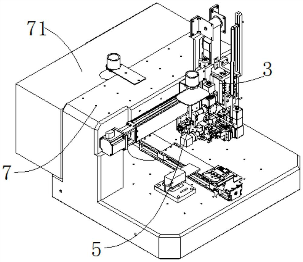
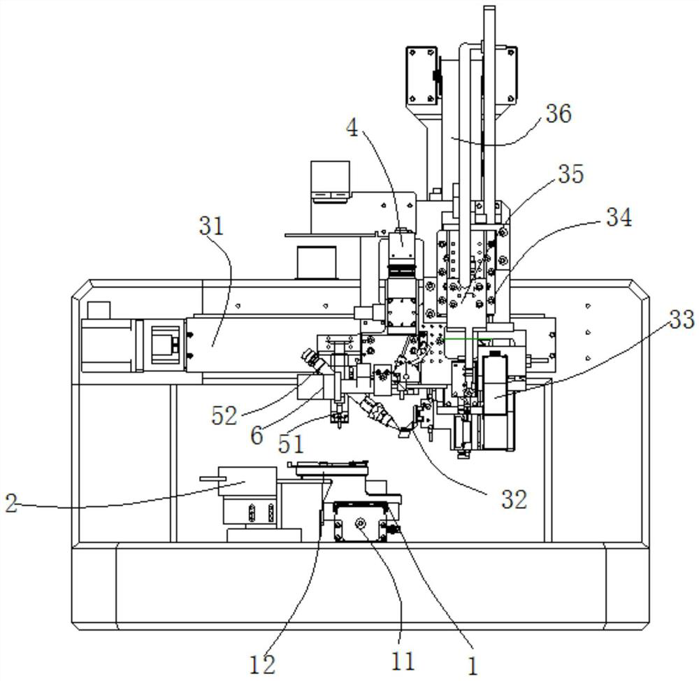
[0040] The glass lens bonding machine includes a carrier assembly 1 for loading product A 101 and product B 102, a light source 2 corresponding to the carrier assembly 1, a grabbing assembly 3 arranged above the carrier assembly 1, and a The collimator 4 on the grasping component 3 and used in conjunction with the carrier component 1, the UV dispensing and curing component 5 used in conjunction with the carrier component 1 that is arranged corresponding to the grasping component 3, and the car...


PUM


Abstract

The invention discloses an automatic glass lens laminating method which includes the steps: S1) loading a product A and a product B onto a vehicle component, and detecting the planar angles of the product A and the product B by a collimator; S2) grabbing the product A by a material taking suction head, detecting and adjusting the consistency of the planar angles of the product A and the product Bby the aid of a two-dimensional angle measuring device; S3) starting a light source, and simultaneously starting a monitoring camera; S4) dispensing glue at a fitting position on the product B by a UV(ultraviolet) dispensing and curing component; S5) driving the grabbed product A to fit with the fitting position on the product B by the grabbing component, and monitoring fitting conditions by themonitoring camera in fitting until a light interference ring is generated between the product A and the product B and the parallelism between the product A and the product B meets requirements; S6) detecting fitting pressure by a pressure feedback device in real time in fitting; S7) performing curing treatment by the UV dispensing and curing component.

Description

technical field [0001] The invention relates to the technical field of automatic equipment and automatic assembly. Specifically, it shows a glass lens laminating machine, and at the same time, it also shows an automatic laminating method for glass lenses using the glass lens laminating machine for automatic laminating of glass lenses. Background technique [0002] With the development of economy and technology, the use of automation equipment in industrial production is becoming more and more extensive. In the automation assembly technology, the assembly of some products needs to be improved; [0003] like figure 1 The assembly 100 shown includes product A 101 and product B 102 which are made of glass lenses and are attached to each other. Both product A 101 and product B 102 are made of glass; the current assembly method cannot guarantee that product A101 and product B 102 The parallelism between product B 102, and in the field of optics, the use of this product needs to e...

Claims


Application Information

Patent Timeline
Patent Type & Authority Patents(China)
IPC IPC(8): C03C27/00F16B11/00
CPCC03C27/00F16B11/006
Inventor 刘鸿铭罗生威
Owner SUZHOU MAKING INTELLIGENT EQUIP CO LTD
Learn More