Expansion joint cutting equipment for bridge construction

A technology of cutting equipment and expansion joints, used in bridge construction, bridges, erection/assembly of bridges, etc. It can solve the problems of low cutting efficiency, complicated operation, and inability to deal with dust in the surrounding environment, and achieve high cutting efficiency.

Inactive Publication Date: 2018-05-15
程新锋
View PDF7 Cites 10 Cited by
  • Summary
  • Abstract
  • Description
  • Claims
  • Application Information

AI Technical Summary

Problems solved by technology

[0005] In order to overcome the shortcomings of the existing slitting equipment for bridge construction, such as low slitting efficiency, complex operation, and inability to reduce dust in the surrounding environment, the tech

Method used


Image

  • Expansion joint cutting equipment for bridge construction
  • Expansion joint cutting equipment for bridge construction
  • Expansion joint cutting equipment for bridge construction

Examples


Example Embodiment

[0031] Example 1

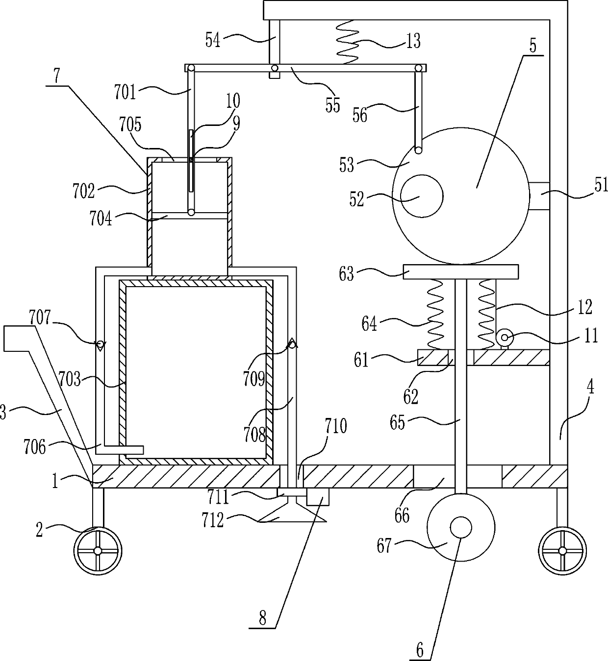
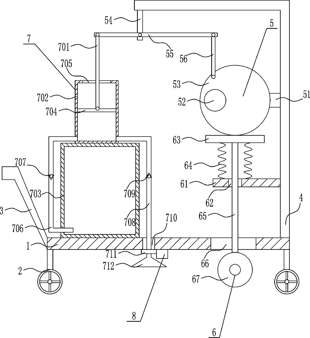
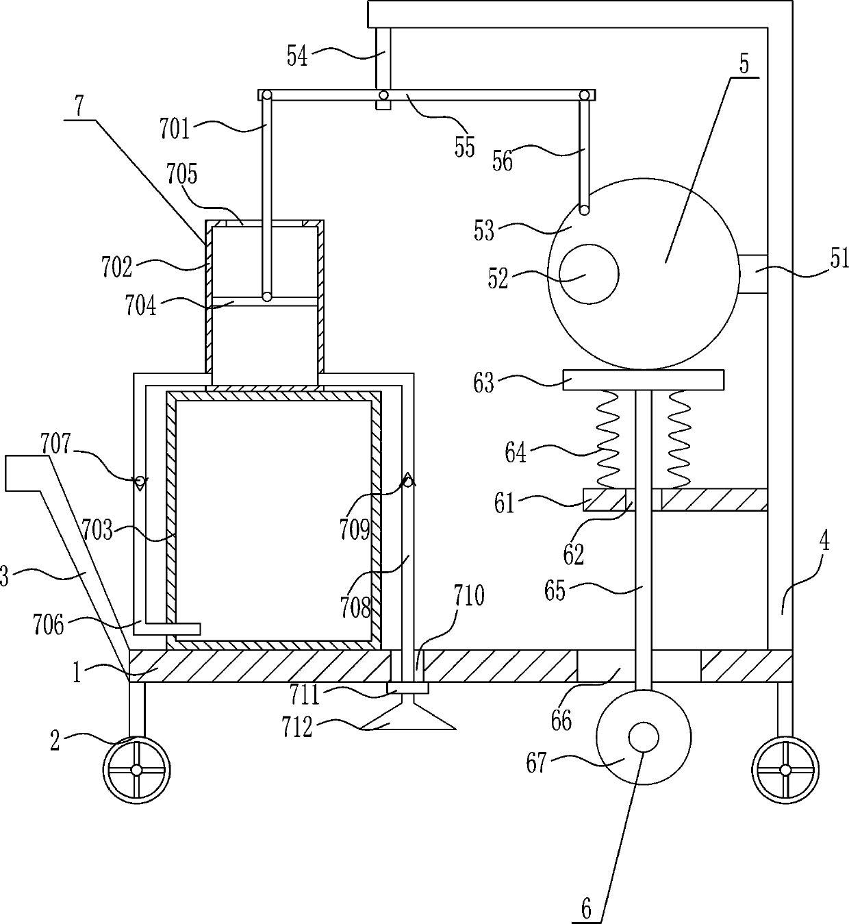
[0032] An expansion joint cutting equipment for bridge construction, such as Figure 1-4 As shown, it includes a bottom plate 1, a wheel 2, a pusher 3, a right bracket 4, a driving mechanism 5, a cutting mechanism 6 and a dust reduction mechanism 7. The bottom of the bottom plate 1 is provided with wheels 2, the left end of the bottom plate 1 is connected with a pusher 3, and the top right of the bottom plate 1 A right support 4 is provided on the side, a driving mechanism 5 is provided on the upper left side of the right support 4, a cutting mechanism 6 is provided on the lower left side of the right support 4, and a dust reduction mechanism 7 is provided on the top left side of the bottom plate 1.

Example Embodiment

[0033] Example 2

[0034] An expansion joint cutting equipment for bridge construction, such as Figure 1-4 As shown, it includes a bottom plate 1, a wheel 2, a pusher 3, a right bracket 4, a driving mechanism 5, a cutting mechanism 6 and a dust reduction mechanism 7. The bottom of the bottom plate 1 is provided with wheels 2, the left end of the bottom plate 1 is connected with a pusher 3, and the top right of the bottom plate 1 A right support 4 is provided on the side, a driving mechanism 5 is provided on the upper left side of the right support 4, a cutting mechanism 6 is provided on the lower left side of the right support 4, and a dust reduction mechanism 7 is provided on the top left side of the bottom plate 1.

[0035] The driving mechanism 5 includes a first support rod 51, a first motor 52, a disc 53, a second support rod 54, a swing rod 55 and a first connecting rod 56. The upper left side of the right support 4 is provided with a first support rod 51, A first motor 52 ...

Example Embodiment

[0036] Example 3

[0037] An expansion joint cutting equipment for bridge construction, such as Figure 1-4 As shown, it includes a bottom plate 1, a wheel 2, a pusher 3, a right bracket 4, a driving mechanism 5, a cutting mechanism 6 and a dust reduction mechanism 7. The bottom of the bottom plate 1 is provided with wheels 2, the left end of the bottom plate 1 is connected with a pusher 3, and the top right of the bottom plate 1 A right support 4 is provided on the side, a driving mechanism 5 is provided on the upper left side of the right support 4, a cutting mechanism 6 is provided on the lower left side of the right support 4, and a dust reduction mechanism 7 is provided on the top left side of the bottom plate 1.

[0038] The driving mechanism 5 includes a first support rod 51, a first motor 52, a disc 53, a second support rod 54, a swing rod 55 and a first connecting rod 56. The upper left side of the right support 4 is provided with a first support rod 51, A first motor 52 ...


PUM


Abstract

The invention relates to expansion joint cutting equipment, in particular expansion joint cutting equipment for bridge construction. The expansion joint cutting equipment comprises a bottom plate andthe like and is characterized in that wheels are arranged at the bottom of the bottom plate, a push handle is connected to the left end of the bottom plate, a right support is arranged on the right side of the top of the bottom plate, a drive mechanism is arranged on the upper portion of the left side of the right support, a cutting mechanism is arranged on the lower portion of the left side of the right support, and a dust suppression mechanism is arranged on the left side of the top of the bottom plate. The expansion joint cutting equipment has the advantages that the equipment is high in joint cutting efficiency, simple to operate and capable of achieving ambient-environment dust suppression; the drive mechanism is used as the main power source to simultaneously drive the cutting mechanism to cut a road surface and the dust suppression mechanism to perform ambient-environment dust suppression, and the spraying range can be increased.

Description

technical field [0001] The invention relates to an expansion joint cutting device, in particular to an expansion joint cutting device for bridge construction. Background technique [0002] Bridges generally refer to structures erected on rivers, lakes and seas to allow vehicles and pedestrians to pass smoothly. In order to adapt to the modern high-speed development of the transportation industry, bridges are also extended to buildings that cross mountain streams, poor geology or meet other transportation needs to make traffic more convenient. A bridge is generally composed of a superstructure, a substructure, a support and ancillary structures. The superstructure is also called a bridge span structure, which is the main structure for crossing obstacles; the substructure includes abutments, piers and foundations; Or the force transmission device installed at the supporting place of the bridge abutment; the auxiliary structures refer to the bridge head board, conical slope pr...

Claims


Application Information

Patent Timeline
IPC IPC(8): E01C23/09E01D21/00B01D47/06
CPCE01C23/0933B01D47/06E01D21/00
Inventor 席佳秀贺蔚敏张凯崔宏发
Owner 程新锋
Why Eureka
Try Eureka