
Sub-frame post-cast joint with external permanent aluminum plate outer mold

A sub-frame and permanent technology, which is applied to post-cast joints and construction fields with permanent aluminum plates outside the sub-frame, and can solve problems such as cross-sections that cannot meet architectural requirements, sub-frame vertical discontinuity, and structural stress. , to achieve the effect of saving labor and construction period, less consumables and good self-flowing performance

Active Publication Date: 2016-09-21
浙江新曙光建设有限公司
View PDF5 Cites 2 Cited by
  • Summary
  • Abstract
  • Description
  • Claims
  • Application Information

AI Technical Summary

Problems solved by technology

If the building is constructed from bottom to top according to the ordinary method, after the building reaches a certain height, under the action of vertical load, due to the vertical discontinuity of the secondary frame, the main frame beams are not only supported on the lower secondary frame columns, but also bear the upper secondary frame. The internal force of the frame columns and the main frame beams of the lower floors will be very large, and the cross-section cannot meet the architectural requirements, and the structural force is not guaranteed

Method used


Image

  • Sub-frame post-cast joint with external permanent aluminum plate outer mold
  • Sub-frame post-cast joint with external permanent aluminum plate outer mold
  • Sub-frame post-cast joint with external permanent aluminum plate outer mold

Examples


Embodiment Construction

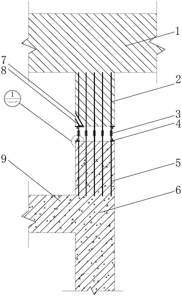
[0037] In this embodiment, the installation process requirements of the concrete pouring formwork, the construction technical requirements of steel bar binding, the construction process requirements of concrete pouring, the welding process requirements, etc. will not be described in detail, and the emphasis will be on the external permanent aluminum plate external formwork involved in the secondary frame of the present invention. Implementation mode of pouring node construction.

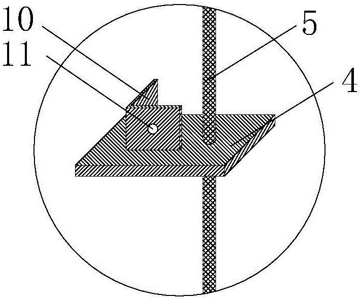
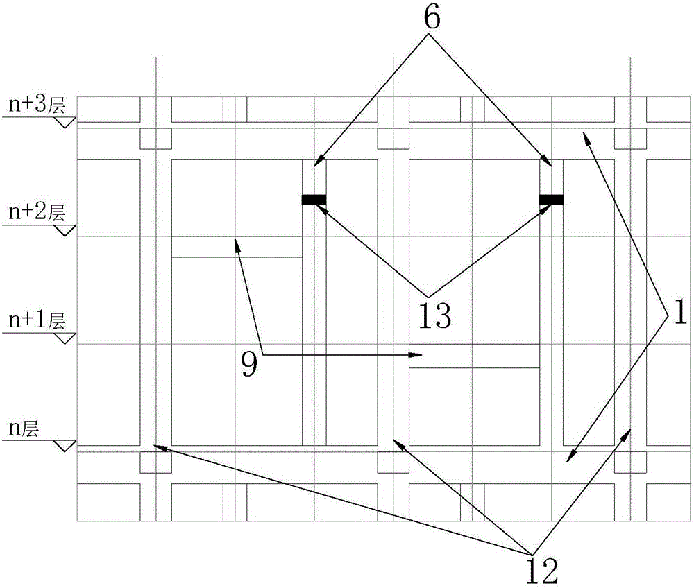
[0038] figure 1 It is a cross-sectional view of the structure before pouring of the post-cast node of the external permanent aluminum plate external mold of the secondary frame of the present invention, figure 2 yes figure 1 A zoom-in diagram of the middle node, image 3 is a schematic diagram of post-pouring node location distribution, Figure 4 It is a cross-sectional view of the structure of the temporary filler of the present invention after installation, Figure 5 It is a structural section...


PUM


Abstract

The invention relates to a sub-frame post-cast joint with an external permanent aluminum plate outer mold. The sub-frame post-cast joint mainly comprises a sub-frame column, steel bar connection sleeves, aluminum plate connectors, an external aluminum plate, a prefabricated grouting material opening, a steel screen and connecting bolts. The post-cast joint is arranged on the sub-frame column to separate the sub-frame column into two parts. The aluminum plate connectors are welded to the upper reinforcing steel bars and the lower reinforcing steel bars of the sub-frame column, and the upper reinforcing steel bars and the lower reinforcing steel bars are connected through the steel bar connection sleeves. The prefabricated grouting material opening is welded in one upper reinforcing steel bar of the sub-frame column. The external aluminum plate is fixedly connected with the aluminum plate connectors through the connecting bolts and self-fixed in an enclosed manner through anchoring screws. Grouting material fills the space formed by the external aluminum plate and the steel screen in an enclosed manner. A leveling concrete layer is arranged outside the external aluminum plate. The sub-frame post-cast joint has the advantages that a main structure and a sub-structure are completely disconnected first to allow the main frame to subside sufficiently and allow a sub-frame to be unstressed, and structure safety is guaranteed. The invention further provides a construction method of the sub-frame post-cast joint.

Description

technical field [0001] The invention relates to a post-cast node and a construction method of a secondary frame with a permanent aluminum plate external formwork. It belongs to the field of main structure engineering, and is suitable for super-high structural systems with high requirements on bearing capacity and strict requirements on the shape and size of buildings. Background technique [0002] With the development of the construction industry, there are more and more beautiful and individual super high-rise buildings, but the premise is that the safety of the structure must be guaranteed. Different parts of the structure carry out different force divisions according to their own bearing capacity, which can greatly improve the bearing capacity of the structure. Setting post-cast nodes in the structural system is just the way to solve the division of labor of different components. [0003] For example, the lattice frame of the peripheral structure in a super high buildin...

Claims


Application Information

Patent Timeline
IPC IPC(8): E04B1/21E04C5/16E04G13/02
CPCE04B1/21E04B1/215E04C5/165E04G13/02
Inventor 王新泉
Owner 浙江新曙光建设有限公司
Learn More