Assembled concrete component reinforcement magnetic suspension connecting and positioning device

A positioning device and concrete technology, applied in building construction, construction, building materials processing and other directions, can solve the problem of difficult to ensure the coaxial butt joint of non-grouting connecting steel bars and grouting connecting steel bars, weakening the load transfer of the connecting parts of the components, and the sleeves. The connection strength decreases and other problems, to avoid relative horizontal displacement, facilitate disassembly and assembly, and ensure the safety of electricity use

Active Publication Date: 2018-05-15
HEFEI CONSTR ENG GRP
View PDF8 Cites 2 Cited by
  • Summary
  • Abstract
  • Description
  • Claims
  • Application Information

AI Technical Summary

Problems solved by technology

The core and difficult point of the connection of prefabricated concrete members is the quality of the connection of the steel bars in the upper and lower concrete members. The existing technology and process are difficult to ensure that the non-grouting connecting steel bars and the grouting connecting steel bars are coaxially connected in the grouting sleeve.
According to statistics, in actual engineering, the accurate centering connection rate between the sleeve and the grouted connecting steel bar is about 20%. The main reasons are as follows: 1) It is difficult to insert the grouted connecting steel bar at the end of the same component into the corresponding sleeve, which makes the installation of the component difficult ;2) When the steel bar of the grouting connection section is inserted into the grouting sleeve, it is close to the inner wall of the sleeve. During subsequent grouting, the grout cannot completely wrap the steel bar of the grouting connection section, so that the connection strength of the sleeve is greatly reduced, and the connection part of the component is seriously weakened. load transfer

Method used


Image

  • Assembled concrete component reinforcement magnetic suspension connecting and positioning device
  • Assembled concrete component reinforcement magnetic suspension connecting and positioning device
  • Assembled concrete component reinforcement magnetic suspension connecting and positioning device

Examples


Embodiment 1

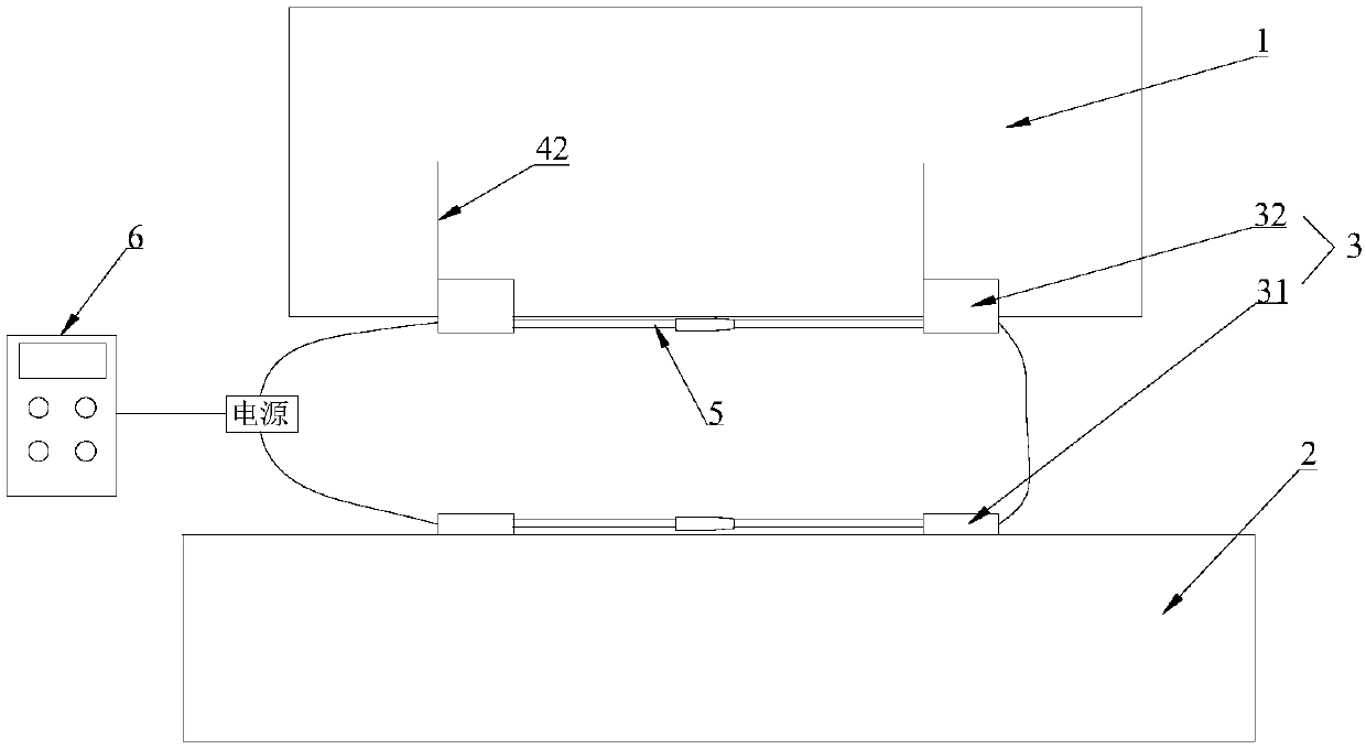
[0037] Such as figure 1 , figure 2 , image 3 , Figure 4 , Figure 5 As shown, a prefabricated concrete member steel bar magnetic levitation connection positioning device is used to position the upper concrete member 1 and the lower concrete member 2, so that the non-grouted connecting steel bars in the upper concrete member 1 and the grouted connecting steel bars in the lower concrete member 2 coaxial.

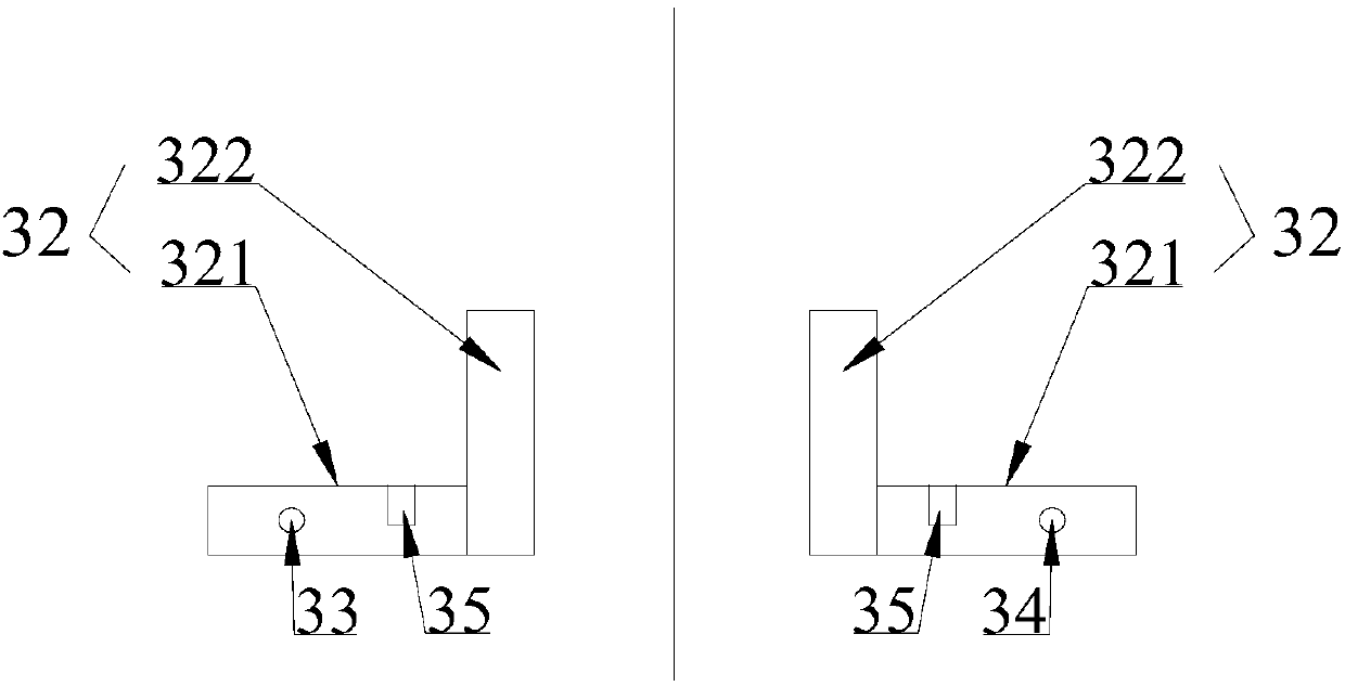
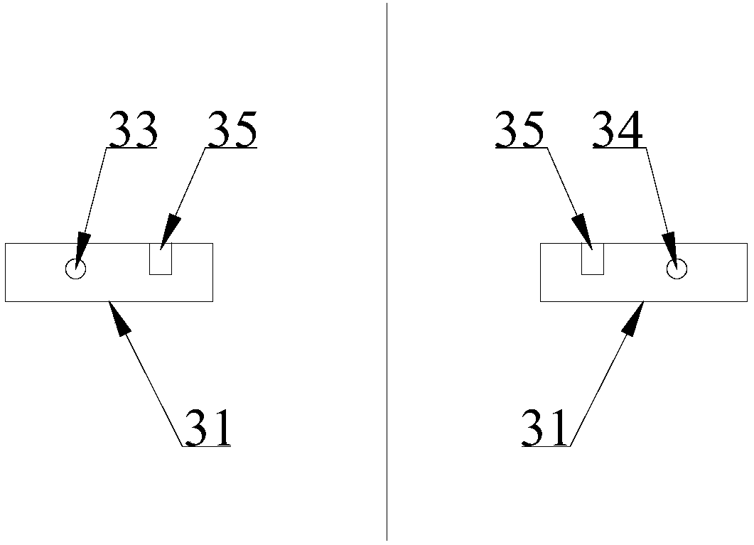
[0038] The positioning device includes a control mechanism 6, at least two groups of support mechanisms 3, and a positioning mechanism 4; the support mechanism 3 includes a lower support 31 and an upper support 32; the upper support 32 includes a supporting plate 321 and a limit plate 322; The plate 322 is vertically fixed on the end of the supporting plate 321, forming an L-shaped structure with the supporting plate 321; the supporting plate 321 and the lower support 31 are both electromagnets; the positioning mechanism 4 is included on the assembly surface of the uppe...

Embodiment 2

[0047] A prefabricated concrete member reinforcement magnetic levitation connection positioning method, comprising the following steps:

[0048] Step 1. Marking: setting at least two first marks on the assembly surface of the lower concrete member 2, and setting second marks corresponding to the number and position of the first marks on the side wall of the upper concrete member 1;

[0049] Step 2. Rough centering: first hoist the upper concrete member 1 to the set position, carry out rough centering of the upper and lower concrete members, and place the lower support 31 and the upper support 32 respectively at the first mark and the second mark , the supporting plate 321 and the lower supporting plate 31 on the upper supporting 32 are all electromagnets, and they are placed opposite to the magnetic poles, and the inner coils of the lower supporting 31 and the supporting plate 321 are connected in series on the same circuit; two adjacent upper supporting The support 32 and the...


PUM


Abstract

The invention provides an assembled concrete component reinforcement magnetic suspension connecting and positioning device which is used for positioning an upper concrete component and a lower concrete component, so that upper and lower reinforcements to be connected are in coaxial butt joint. The device comprises a control mechanism, at least two groups of support mechanisms, a positioning mechanism and a support mechanism, the supporting mechanism comprises a lower support and an upper support, the upper support comprises a support plate and a limit plate, both the support plate and the lower support are electromagnets, like magnetic poles of the support plate and the lower support are oppositely placed, the positioning mechanism comprises a first mark and a second mark which are arranged at corresponding positions of assembly surfaces of the upper concrete component and the lower concrete component, the lower support is placed at the first mark, the upper support is placed at the second mark, coils in the support plate and the lower support are serially connected onto the same circuit, the support mechanisms can be the same in magnetic force, support stability is ensured, and the control mechanism is used for controlling the magnetic force of the electromagnets. By the aid of the principle of magnetic suspension, the reinforcements of the upper concrete component and the lower concrete component are rapidly and accurately centered.

Description

technical field [0001] The invention belongs to the field of prefabricated buildings, in particular to a magnetic levitation prefabricated concrete member reinforcement connection positioning device. Background technique [0002] The biggest feature of prefabricated buildings is green construction, energy saving and environmental protection. The prefabricated concrete components used are assembled and connected at the construction site, which can avoid or reduce the impact of construction on the surrounding environment. The high degree of mechanization can greatly shorten the construction period and reduce construction costs. On-site labor resource input. From the perspective of the global environment, it is imperative for the construction industry to develop into a prefabricated construction method. [0003] The prefabricated concrete structure refers to the concrete structure assembled by prefabricated concrete components through reliable connection, and then the prefabri...

Claims


Application Information

Patent Timeline
Patent Type & Authority Applications(China)
IPC IPC(8): E04G21/12E04G21/18
CPCE04G21/122E04G21/1841
Inventor 郑志涛王玉国
Owner HEFEI CONSTR ENG GRP
Why Eureka
Try Eureka