Mine draw shaft system
A technology for shafts and mines, which is applied in the field of mining engineering, and can solve problems such as increased project investment costs and increased vein-piercing projects
- Summary
- Abstract
- Description
- Claims
- Application Information
AI Technical Summary
Problems solved by technology
Method used
Image

Examples
Embodiment 1
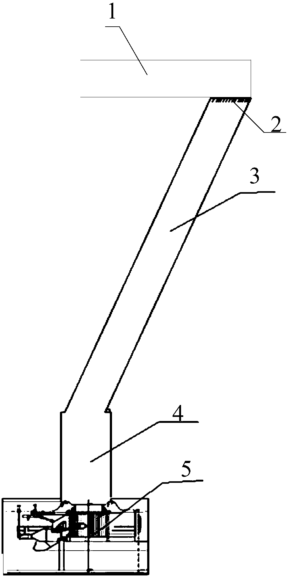
[0027] This embodiment provides a mine shaft system, such as figure 2 As shown, the chute system includes: feeding conveying channel 1, screening equipment 2, first chute 3, second chute 4 and discharge conveying channel 5;
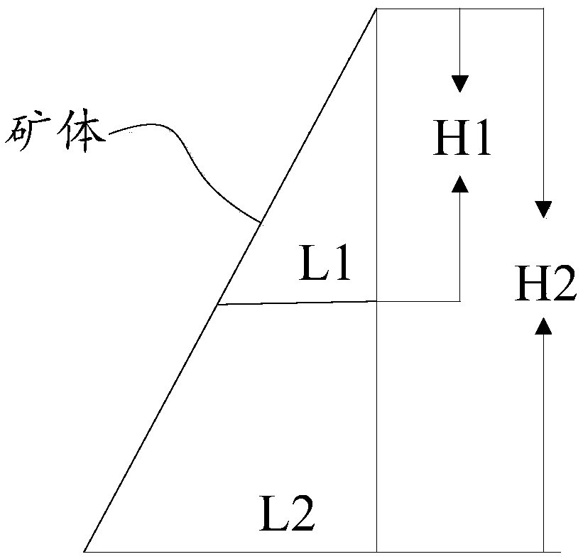
[0028] The feeding conveying channel 1 is connected to one end of the first chute 3; one end of the first chute 3 is the inlet end of the first chute 3; the screening equipment 2 is installed at one end of the first chute 3; The other end of the first chute 3 is connected with one end of the second chute 4; the discharge conveying channel 5 is located below the other end of the second chute, and is used for utilizing the rail mine car to transport the ore; in order to reduce the distance through the veins, the The first chute 3 is an inclined chute; in order to effectively form the center falling ore and reduce the wear of the second chute, the second chute 4 is a straight chute.
[0029] Here, the inclination angle of the first chute 3 includes: 65° to...
Embodiment 2
[0038] In practical application, when using the chute system provided in Embodiment 1 to transport mineral materials to a certain mine, the specific implementation is as follows:
[0039] same as figure 2 As shown, the chute system includes: feeding conveying channel 1, screening equipment 2, first chute 3, second chute 4 and discharge conveying channel 5;
[0040] The feeding conveying channel 1 is connected to one end of the first chute 3; one end of the first chute 3 is the inlet end of the first chute 3; the screening equipment 2 is installed at one end of the first chute 3; The other end of the first chute 3 is connected with one end of the second chute 4; the discharge conveying channel 5 is located below the other end of the second chute, and is used for utilizing the rail mine car to transport the ore; in order to reduce the distance through the veins, the The first chute 3 is an inclined chute; in order to effectively form the center falling ore and reduce the wear ...
Embodiment 3
[0050] In practical application, when using the chute system provided in Embodiment 1 to transport mineral materials to another mine, the specific implementation is as follows:
[0051] same as figure 2 As shown, the chute system includes: feeding conveying channel 1, screening equipment 2, first chute 3, second chute 4 and discharge conveying channel 5;
[0052] The feeding conveying channel 1 is connected to one end of the first chute 3; one end of the first chute 3 is the inlet end of the first chute 3; the screening equipment 2 is installed at one end of the first chute 3; The other end of the first chute 3 is connected with one end of the second chute 4; the discharge conveying channel 5 is located below the other end of the second chute, and is used for utilizing the rail mine car to transport the ore; in order to reduce the distance through the veins, the The first chute 3 is an inclined chute; in order to effectively form the center falling ore and reduce the wear of...
PUM
 Abstract
Description
Claims
Application Information
 - R&D
- Intellectual Property
- Life Sciences
- Materials
- Tech Scout
- Unparalleled Data Quality
- Higher Quality Content
- 60% Fewer Hallucinations
Browse by: Latest US Patents, China's latest patents, Technical Efficacy Thesaurus, Application Domain, Technology Topic, Popular Technical Reports.
© 2025 PatSnap. All rights reserved.Legal|Privacy policy|Modern Slavery Act Transparency Statement|Sitemap|About US| Contact US: help@patsnap.com