Aero-engine formed by 3D printing

An aero-engine and 3D printing technology, which is applied in the direction of engine components, engine cooling, machine/engine, etc., can solve problems such as inability to achieve heat dissipation, simple structure, and heavy weight of aero-engines

Pending Publication Date: 2018-05-15
深圳市华阳新材料科技有限公司
View PDF0 Cites 4 Cited by
  • Summary
  • Abstract
  • Description
  • Claims
  • Application Information

AI Technical Summary

Problems solved by technology

[0003] However, the weight of the aero-engine obtained by adopting the prior art is relatively large, thereby causing its thrust to be reduced, and the components of the aero-engine obtained by the prior art are simple in structure and cannot achieve good heat dissipation. Therefore, it is urgently needed A new type of aero-engine with light weight, high thrust and good heat dissipation effect

Method used


Image

  • Aero-engine formed by 3D printing
  • Aero-engine formed by 3D printing
  • Aero-engine formed by 3D printing

Examples


Embodiment approach

[0048] According to a preferred embodiment of the present invention, the compressor housing 1 has a height of 25-65 mm, preferably 30-60 mm, more preferably 35-55 mm.

[0049] According to a preferred embodiment of the present invention, the wall thickness of the compressor housing 1 is 0.1-0.5 mm, preferably 0.2-0.4 mm.

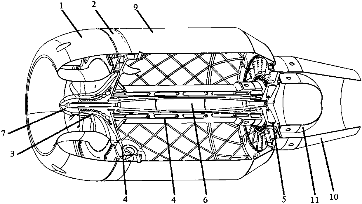
[0050] Wherein, the compressor casing 1 of the present invention is preferably made by 3D printing, so that a thin-walled compressor casing can be obtained, and the compressor casing 1 can be given a lighter weight.

[0051] In the present invention, in the compressor housing 1 , the junction of the annular outer surface and the annular inner surface is defined as the upper end of the compressor housing, and the bottom surface is defined as the lower end of the compressor housing. The "sector" in the "fan-shaped hole" refers to a part of the circular ring, that is, a part of the circular ring, such as Figure 7 Shown in 112.

[0052] According to a preferr...


PUM

PropertyMeasurementUnit
Wall thicknessaaaaaaaaaa

Abstract

Disclosed is an aero-engine formed by 3D printing. The aero-engine formed by 3D printing comprises a compressor shell (1), a radial diffuser (2), an impeller (3), an axial diffuser (4), a turbine (5)and a turbine shaft (6). The radial diffuser (2) is of a hollow disc-shaped structure, and the impeller (3) is arranged in the center of the radial diffuser (2). The axial diffuser (4) is of a hollowstructure, the turbine shaft (6) is arranged in the axial diffuser (4), and the two ends of the turbine shaft (6) are connected with the impeller (3) and the turbine (5) correspondingly. The aero-engine formed by 3D printing further comprises a shaft end nut (7), a stop ring (8), an engine shell (9), a tail jet outer shell (10) and a tail jet inner shell (11). Parts of the aero-engine formed by 3Dprinting are manufactured by 3D printing, and have the small wall thicknesses, then the light weight is given to the aero-engine, and therefore the carrying capacity of the aero-engine is improved under the condition of the same thrust.

Description

technical field [0001] The invention belongs to the field of aero-engines, and relates to aero-engines, in particular to a 3D printing aero-engine. Background technique [0002] An aero-engine is an engine that provides the power required for aircraft to fly. Unlike engines in other application fields, the weight of an aero-engine is a key factor affecting the flight power of an aircraft. Under the premise of ensuring the strength of use, the weight of the engine should be reduced as much as possible, so that more payload can be achieved under the same thrust. [0003] However, the weight of the aero-engine obtained by adopting the prior art is relatively large, thereby causing its thrust to be reduced, and the components of the aero-engine obtained by the prior art are simple in structure and cannot achieve good heat dissipation. Therefore, it is urgently needed A new type of aero-engine with light weight, high thrust and good heat dissipation. Contents of the invention ...

Claims


Application Information

Patent Timeline
IPC IPC(8): F02C7/18F02C7/00B33Y80/00
CPCF02C7/00F02C7/18B33Y80/00
Inventor 韩向阳易智邵犬
Owner 深圳市华阳新材料科技有限公司
Why Eureka
Try Eureka