Automobile body rear floor frame structure

A floor frame and rear floor technology, which is applied to the superstructure, superstructure sub-assemblies, vehicle components, etc., can solve the problems of a large number of rear floor beam parts and poor welding accuracy.

Pending Publication Date: 2018-05-18
GUANGZHOU AUTOMOBILE GROUP CO LTD
View PDF0 Cites 9 Cited by
  • Summary
  • Abstract
  • Description
  • Claims
  • Application Information

AI Technical Summary

Problems solved by technology

[0003] The purpose of the present invention is to provide a rear floor frame structure of a car body to solve the problem that the rear floor beam of the existing car body rear floor frame structure is composed of multiple steel parts such as the upper joint of the rear floor cross beam and the lower joint of the rear floor

Method used


Image

  • Automobile body rear floor frame structure
  • Automobile body rear floor frame structure
  • Automobile body rear floor frame structure

Examples


Embodiment Construction

[0026] The specific implementation manners of the present invention will be further described in detail below in conjunction with the accompanying drawings and embodiments. The following examples are used to illustrate the present invention, but are not intended to limit the scope of the present invention.

[0027] In the description of the present invention, directions such as up, down, left, right, front and back, and descriptions of top and bottom are all for figure 1 As a limitation, when the placement of the rear floor frame structure of the vehicle body changes, its corresponding orientation and top and bottom descriptions will also change according to the change of placement, and the present invention will not repeat them here.

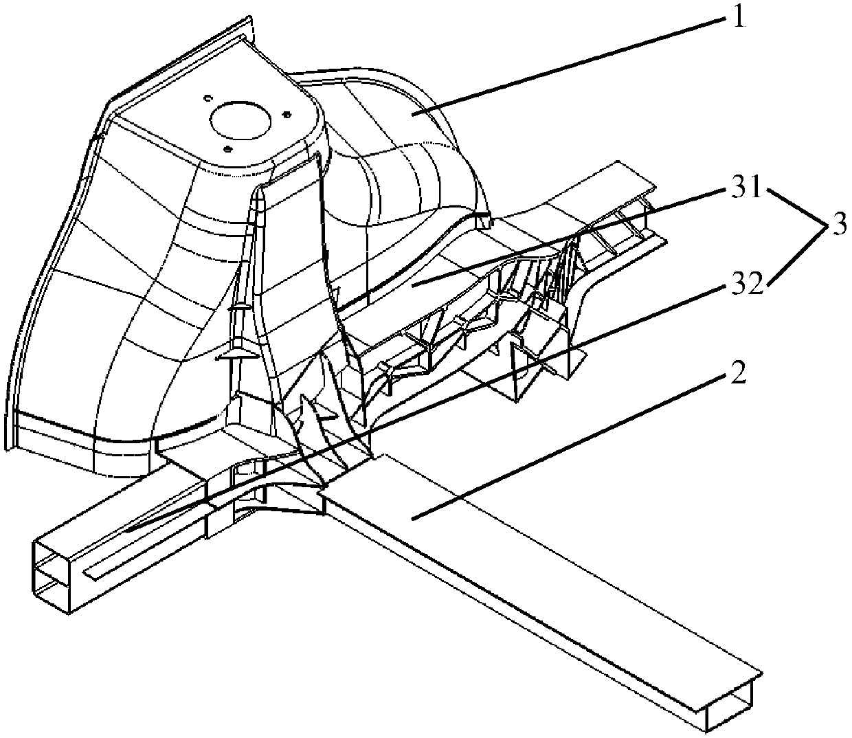
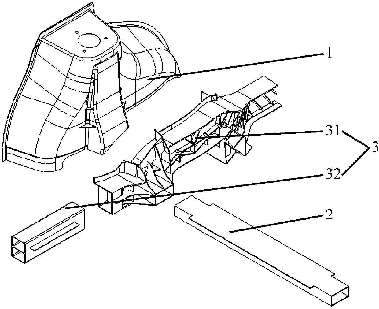
[0028] to combine Figure 1 to Figure 6 As shown, a vehicle body rear floor frame structure 100 according to a preferred embodiment of the present invention includes a rear wheel house 1, a rear floor beam 2 and a rear longitudinal beam 3, and...


PUM


Abstract

The invention relates to the technical field of automobile bodies and discloses an automobile body rear floor frame structure. The automobile body rear floor frame structure comprises a rear wheel casing, a rear floor crossbeam and a rear longitudinal beam. The rear longitudinal beam comprises a rear longitudinal beam front section and a rear longitudinal beam rear section. The rear longitudinal beam front section comprises a rear longitudinal beam front section body and a joint structure connected with the rear longitudinal beam front section body, and the rear longitudinal beam front sectionbody and the joint structure are integrally cast and formed through an aluminum alloy. The rear wheel casing, the rear floor crossbeam and the rear longitudinal beam rear section are connected to thejoint structure. Due to the fact that the rear longitudinal beam front section body and the joint structure are integrally cast and formed through the aluminum alloy, the joint structure can be integrated on the rear longitudinal beam front section body, a rear floor crossbeam joint spliced by multiple steel parts such as a rear floor crossbeam upper joint and a rear floor crossbeam lower joint is prevented from being arranged on the rear floor crossbeam, the number of parts of the rear floor crossbeam is reduced, a splicing and welding structure on the rear floor crossbeam is simplified, sothat the weight of the rear floor crossbeam is reduced, and the strength and rigidity of the rear floor crossbeam are improved.

Description

technical field [0001] The invention relates to the technical field of automobile bodies, in particular to a rear floor frame structure of a vehicle body. Background technique [0002] At present, the rear floor frame structure of the existing automobile body is mainly composed of rear wheel housings, rear floor beams and rear floor longitudinal beams. The rear floor beams are usually provided with rear floor beam joints, and the rear floor beam joints The upper joint of the rear floor cross beam connected to the wheel house and the lower joint of the rear floor cross beam connected with the rear floor longitudinal beam are spliced ​​together to ensure the connection between the rear floor cross beam and the rear wheel housing and the rear floor longitudinal beam. However, since the rear floor beam joint needs to be spliced ​​by multiple steel parts such as the upper joint of the rear floor beam and the lower joint of the rear floor beam, the number of parts of the rear floo...

Claims


Application Information

Patent Timeline
IPC IPC(8): B62D25/20
CPCB62D25/2027Y02T10/40
Inventor 曾鑫袁焕泉陈东罗培锋林佳武谢锋
Owner GUANGZHOU AUTOMOBILE GROUP CO LTD
Why Eureka
Try Eureka