Intelligent deformed steel bar alignment discharging bracket

A technology of threaded steel and material bracket, which is applied in the direction of object stacking, metal processing, metal processing equipment, etc., can solve the problem of single function of the output bracket, and achieve the effect of sensitive operation, reasonable structure design and improved efficiency

Pending Publication Date: 2018-05-18
天津昭旭鑫荣科技发展有限公司
0 Cites 2 Cited by

AI-Extracted Technical Summary

Problems solved by technology

[0004] In view of this, the present invention aims to propose an intelligent rebar straightening discharge bracket to solve the problem that the discharge bracket of the existing steel bar str...

Method used

...

Abstract

The invention provides an intelligent deformed steel bar alignment discharging bracket. The reinforcing steel bar guide and containing effect can be achieved, reinforcing steel bars can be automatically transferred through driving devices, time and labor are saved, the bracket is quick and convenient, and manpower input is reduced. The intelligent deformed steel bar alignment discharging bracket comprises a groove structure, a sliding device and an installing support; the groove structure comprises a base plate and side plates arranged on the two sides of the base plate, and an opening is formed in the upper end of the groove structure; each side plate comprises a fixed plate and a movable plate, wherein the fixed plate and the base plate are welded and fixed, a cantilever is transverselyerected above the fixed plate, the cantilever and the fixed plate are in shaft connection, and the movable plate and the cantilever are connected through a shaft; and the movable plates are connectedwith the driving devices and are correspondingly provided with the driving devices, each driving device comprises a driving motor and a transmission device, and the driving motors control opening andclosing of the movable plates through the transmission devices.

Application Domain

Technology Topic

Image

  • Intelligent deformed steel bar alignment discharging bracket
  • Intelligent deformed steel bar alignment discharging bracket
  • Intelligent deformed steel bar alignment discharging bracket

Examples

  • Experimental program(1)

Example Embodiment

[0045] It should be noted that the embodiments of the present invention and the features in the embodiments can be combined with each other if there is no conflict.
[0046] In the description of the present invention, it should be understood that the terms "center", "longitudinal", "transverse", "upper", "lower", "front", "rear", "left", "right", " The orientation or positional relationship indicated by "vertical", "horizontal", "top", "bottom", "inner", "outer" etc. is based on the orientation or positional relationship shown in the drawings, and is only for the convenience of describing the present invention and The description is simplified, rather than indicating or implying that the pointed device or element must have a specific orientation, be constructed and operated in a specific orientation, and therefore cannot be understood as a limitation of the present invention. In addition, the terms "first", "second", etc. are only used for descriptive purposes, and cannot be understood as indicating or implying relative importance or implicitly indicating the number of indicated technical features. Therefore, the features defined with "first", "second", etc. may explicitly or implicitly include one or more of these features. In the description of the present invention, unless otherwise specified, "plurality" means two or more.
[0047] In the description of the present invention, it should be noted that the terms "installed", "connected" and "connected" should be understood in a broad sense, unless otherwise clearly specified and limited. For example, they can be fixed or detachable. Connected or integrally connected; it can be a mechanical connection or an electrical connection; it can be directly connected or indirectly connected through an intermediate medium, and it can be the internal communication between two components. For those of ordinary skill in the art, the specific meanings of the above terms in the present invention can be understood through specific situations.
[0048] Hereinafter, the present invention will be described in detail with reference to the drawings and in conjunction with the embodiments.
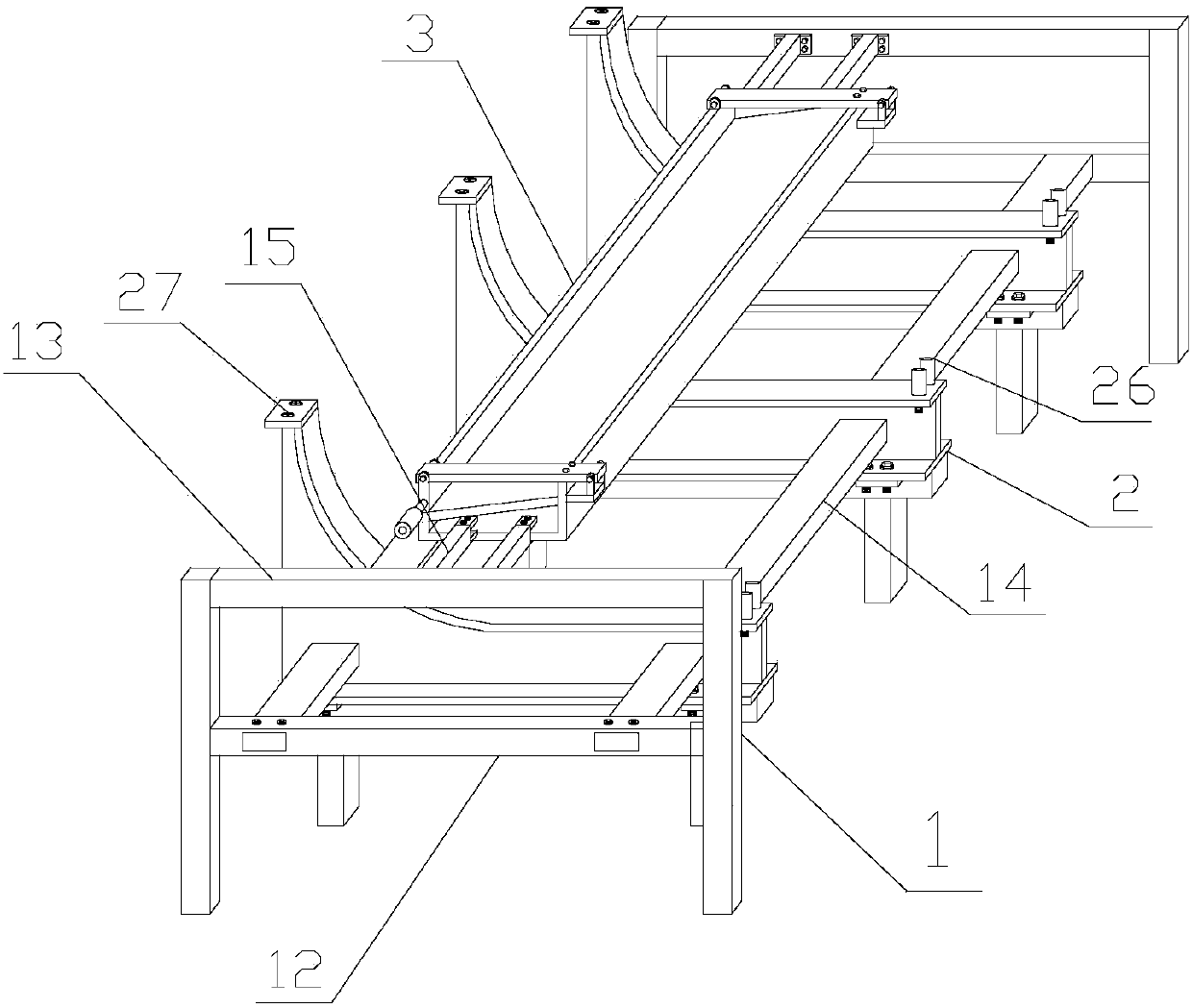
[0049] Such as figure 1 , figure 2 As shown, an intelligent rebar straightening and discharging bracket includes a trough structure 3, a sliding device 2, and a mounting frame 1 for fixing the trough structure 3;
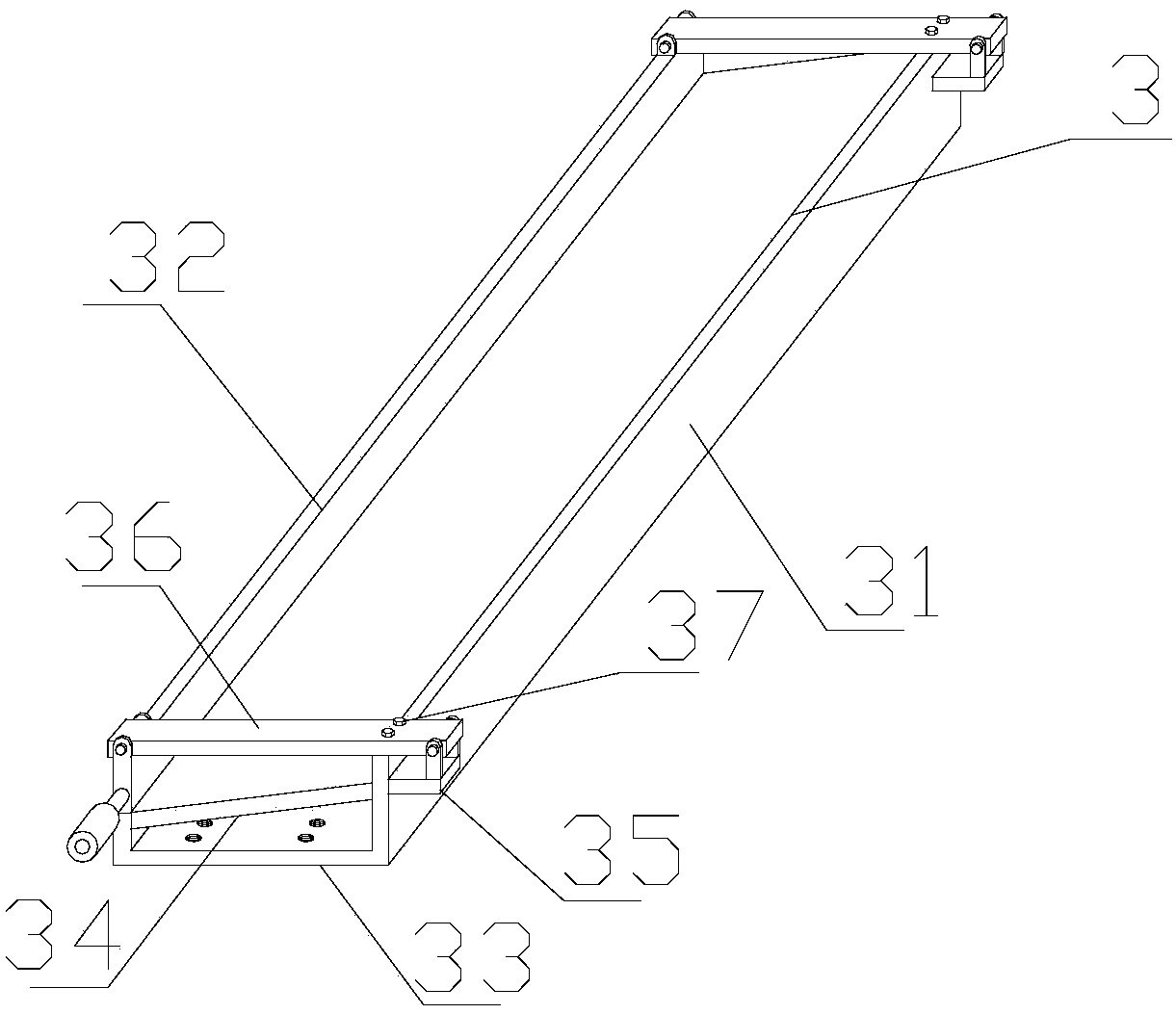
[0050] The trough structure 3 includes a bottom plate and side plates arranged on both sides of the bottom plate. The upper end of the trough structure 3 is open; the side plate includes a fixed plate 31 and a movable plate 32. The fixed plate 31 is welded and fixed to the bottom plate. A cantilever 36 is set laterally above the fixed plate 31, and the cantilever 36 is connected to the fixed plate 31 as a shaft. The movable plate 32 is suspended below one end of the cantilever 36 away from the fixed plate 31. The movable plate 32 It is connected to the cantilever 36 by a shaft; the moving plate 32 is connected to the driving device; the bottom plate is a double-layer structure, including a flat plate 33 and an inclined plate 34, the inclined plate 34 is arranged obliquely above the flat plate 33, A gap is reserved between the inclined plate 34 and the flat plate 33, the moving plate 32 and the fixed plate 31 are perpendicular to the flat plate 33, the inclined plate 34 is inclined toward the moving plate 32; the inclined surface of the inclined plate 34 The bottom is attached to the bottom surface of the movable plate 32, the bottom of the upper surface of the inclined surface is a flat surface, and is installed in close contact with the lower surface of the movable plate 32, leaving a small gap in the middle to facilitate opening and closing, and prevent the steel bar from slipping out through the gap;
[0051] The movable plate 32 is correspondingly provided with a driving device, the driving device includes a driving motor and a transmission device, and the driving motor controls the opening and closing of the movable plate 32 through the transmission device;
[0052] The sliding device 2 is used to slide the steel bars slid out through the movable plate 32 to the target area. If the tank structure is not long enough, the middle can be spliced.
[0053] A horizontal plate 35 is welded transversely to the outside of the fixed plate 31, two baffles are welded on the upper part of the horizontal plate 35, and a rotating shaft is arranged between the two baffles, and the rotating shaft penetrates the end of the cantilever 36; The cantilever 36 is attached to the upper surface of the fixing plate 31 and installed. The joint between the fixing plate 31 and the cantilever 36 is fixed by a fixing bolt 37;
[0054] There are two cantilever arms 36, and the two cantilever arms 36 are respectively arranged at the ends of the trough structure 3;
[0055] The cantilever 36 and the movable plate 32 are connected by a rotating shaft.
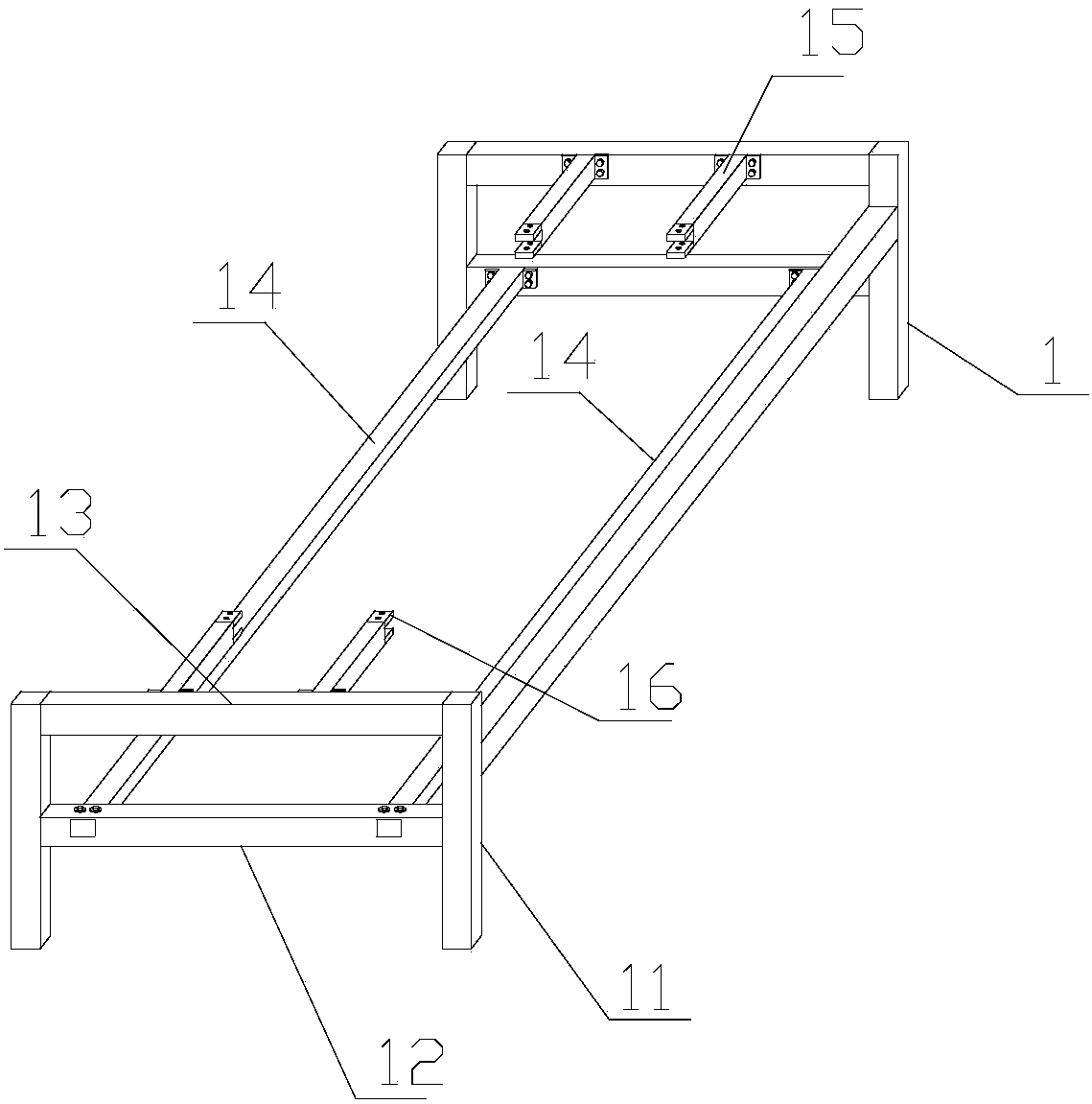
[0056] Such as image 3 As shown, the mounting frame 1 includes supporting legs 11 arranged at both ends of the trough structure 3 for supporting functions, and two supporting legs 11 are provided at each end;
[0057] Two fixed cross beams are installed between the two support legs 11 at each end, including a first cross beam 13 and a second cross beam 12. The first cross beam 13 is laterally fixed between the tops of the two support legs 11. Two cross beams 12 are laterally fixed between the middle positions of the two supporting legs 11;
[0058] The first cross beam 13 is provided with a tank structure fixing device, and the tank structure fixing device is used to fix the tank structure 3; the second cross beam 12 is provided with a sliding device fixing unit, the sliding device fixing unit Used to fix the sliding device 2.
[0059] The trough structure fixing device includes a fixing rod 15 which is laterally fixed on the inner side of the first cross beam 13. One end of the fixing rod 15 is vertically fixed on the first cross beam 13, and the other end is welded with two fixing pieces 16. The two fixing pieces 16 are distributed up and down, there is a gap between the two fixing pieces 16, and the two fixing pieces 16 are provided with corresponding threaded holes. The two fixing pieces 16 are used to clamp the flat The panel 33 is fixed by bolts between the fixing piece 16 and the plane plate 33; each first cross beam 13 is provided with two fixing rods 15.
[0060] The sliding device fixing unit includes a connecting rod 14 which is transversely arranged between two different second beams 12, and the connecting rod 14 penetrates a square hole 25 provided on the sliding device 2, and each connecting rod 14 A plurality of sliding devices 2 are supported on 14; there are two connecting rods 14.
[0061] A connecting piece is welded on both sides of the end of one end of the connecting rod 14. The connecting piece is provided with threaded holes and is fixed on the second beam 12 by bolts; the other end of the connecting rod 14 penetrates the second beam 12, and the second Two bolts penetrating the second cross beam 12 and the connecting rod 14 are provided above the cross beam 12, and the bolts are used for fixing. One end of the connecting rod 14 needs to be inserted into the square hole 25, so the end inserted into the square hole 25 is not provided with a connecting piece, and is fixed on the second cross beam 12 in a plug-in form.
[0062] Such as Figure 4 As shown, the sliding device 2 includes an arc-shaped plate 24, a supporting plate 23, and a flat plate. One side of the arc-shaped plate 24 is arc-shaped, and the bottom of the arc-shaped plate 24 is smoothly connected to the flat plate. The angle between the top and bottom of the plate 24 and the horizontal direction is gradually reduced; the support plate 23 is provided with a structure with the same contour as the arc plate 24, and the arc plate 24 and the flat plate are welded to the support plate 23;
[0063] The supporting plate 23 is provided with square holes 25. There are two square holes 25. The square holes 25 are used to insert the connecting rod 14 of the mounting frame 1; the sliding device 2 can be further fixed by the connecting rod 14.
[0064] The height of the upper end of the arc-shaped plate 24 is higher than the height of the outlet of the steel bar exiting bracket, and there is a gap between the arc-shaped plate 24 and the outlet of the steel bar discharging bracket;
[0065] The bottom of the arc-shaped plate 24 is provided with a support frame; a blocking device 26 is provided above the end of the flat plate away from one end of the arc-shaped plate 24, and the sliding steel bar is blocked by the blocking device 26.
[0066] The support frame includes two vertical rods 21 and a cross rod 22 fixed on the top of the two vertical rods 21, the vertical rod 21 is used to support the cross rod 22, and a support plate 23 is fixedly mounted on the cross rod 22;
[0067] The bottom of the support plate 23 is provided with a parallel connection plate, and the parallel connection plate is horizontally welded to the bottom of the support plate 23;
[0068] Connecting pieces are symmetrically installed on both sides of the cross bar 22, the connecting pieces are provided with threaded holes, the parallel connecting plates are provided with threaded holes corresponding to the connecting pieces, and between the parallel connecting plates and the connecting pieces Secure by bolts.
[0069] A mounting plate 27 is welded to the top ends of the arc plate 24 and the support plate 23, and the side of the mounting plate 27 is on the extended surface of the arc surface of the arc plate 24; the mounting plate 27 is used to install the drive motor and Travel switch, transmission components;
[0070] The drive motor is also correspondingly provided with a travel switch, the travel switch is triggered by a linkage device, and the operating state of the drive motor is changed by the travel switch;
[0071] Such as Figure 5 As shown, the driving motor is also connected to a PLC controller, and the PLC controller is also connected to the straightening machine motor and the hydraulic cutting device of the straightening machine through the driving circuit. The PLC controller is also connected to the rotary encoder and pressure sensor of the straightening machine, and sends the information of the number of cut steel bars through the rotary encoder and pressure sensor to the PLC controller. The PLC controller uses the set number, when the tank structure 3 When the number of stored cut steel bars reaches the specified number, a control signal will be sent to the drive motor, the drive moving plate 32 is opened, the steel bars slide down, and the slide device 2 slides to the specified area.
[0072] The above descriptions are only preferred embodiments of the present invention and are not intended to limit the present invention. Any modification, equivalent replacement, improvement, etc. made within the spirit and principle of the present invention shall be included in the present invention. Within the scope of protection.

PUM

no PUM

Description & Claims & Application Information

We can also present the details of the Description, Claims and Application information to help users get a comprehensive understanding of the technical details of the patent, such as background art, summary of invention, brief description of drawings, description of embodiments, and other original content. On the other hand, users can also determine the specific scope of protection of the technology through the list of claims; as well as understand the changes in the life cycle of the technology with the presentation of the patent timeline. Login to view more.

Similar technology patents

Full-automatic PU (Polyurethane) glue injection machine device for end covers

ActiveCN103924394AEasy to operateReduce human inputAutomatic machinesEngineeringPolyurethane
Owner:BENGBU GAODE MACHINERY AUTOMATION SCI & TECH

Classification and recommendation of technical efficacy words

  • Reduce human input
  • The overall structure design is reasonable

Water-area waste automatic cleaning vessel and method based on machine vision

ActiveCN106741683AReduce human inputReduce job riskWater cleaningEnergy supplyWater areaMachine vision
Owner:CHINA UNIV OF MINING & TECH

Adjustable uterine curet

Owner:QINGDAO WOMEN & CHILDREN HOSPITAL
Why Eureka
Try Eureka