Panel inspection device

A panel inspection and panel technology, applied in the field of panel optical inspection devices, can solve the problems of low efficiency of automatic optical inspection, waste of manpower and material resources, etc., and achieve the effects of reducing labor input, saving manpower and material resources, and improving efficiency

Pending Publication Date: 2018-03-23
KUSN JINGXUN ELECTRONICS TECH
View PDF0 Cites 21 Cited by
  • Summary
  • Abstract
  • Description
  • Claims
  • Application Information

AI Technical Summary

Problems solved by technology

[0004] The purpose of the present invention is to solve the problem of low efficiency of automatic optical detection in the prior art mentioned in the above background technology and the need to consume a lot of manpower and material resources, and to provide a panel detection device

Method used


Image

  • Panel inspection device
  • Panel inspection device
  • Panel inspection device

Examples


Embodiment Construction

[0052] The present invention will be further described in detail below in conjunction with the accompanying drawings and specific embodiments.

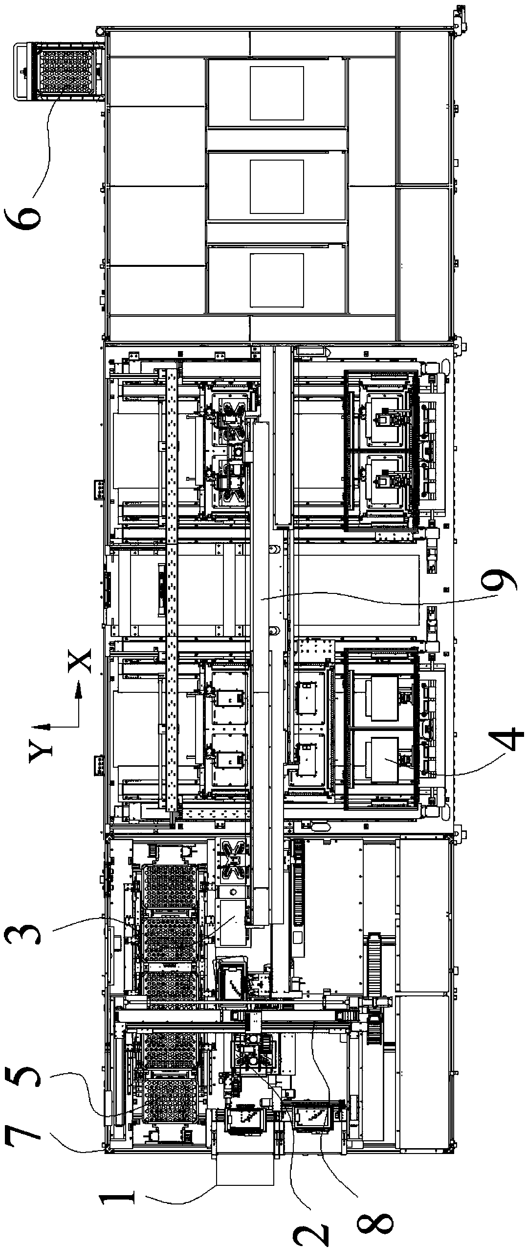
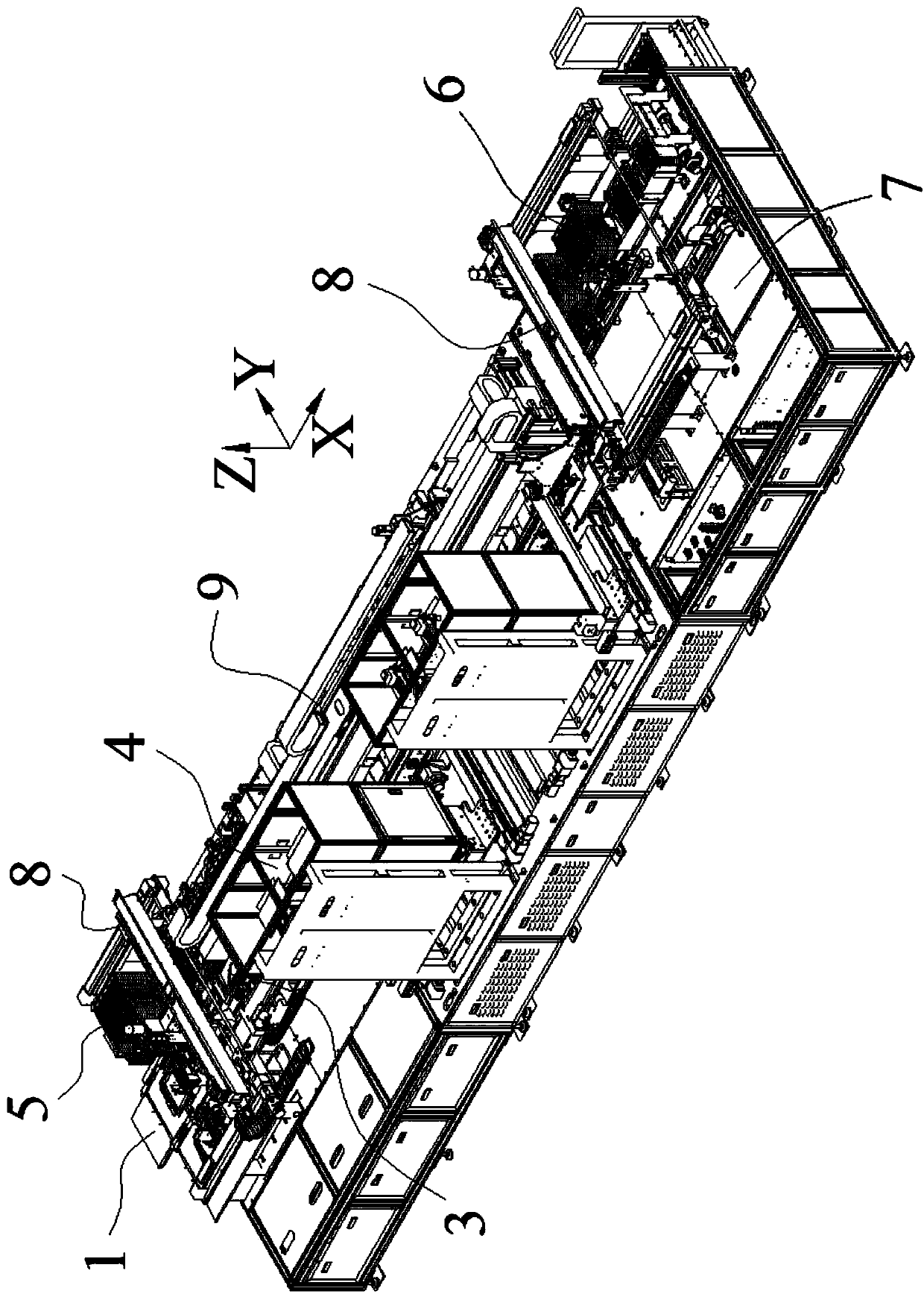
[0053] Such as Figure 1-25 As shown, the panel detection device of this embodiment includes a base 7, which is the fixed basis of the entire panel detection device, and the base 7 is arranged in sequence along the panel conveying direction with a dispatching device 3, an automatic optical detection device 4 and a discharge device .

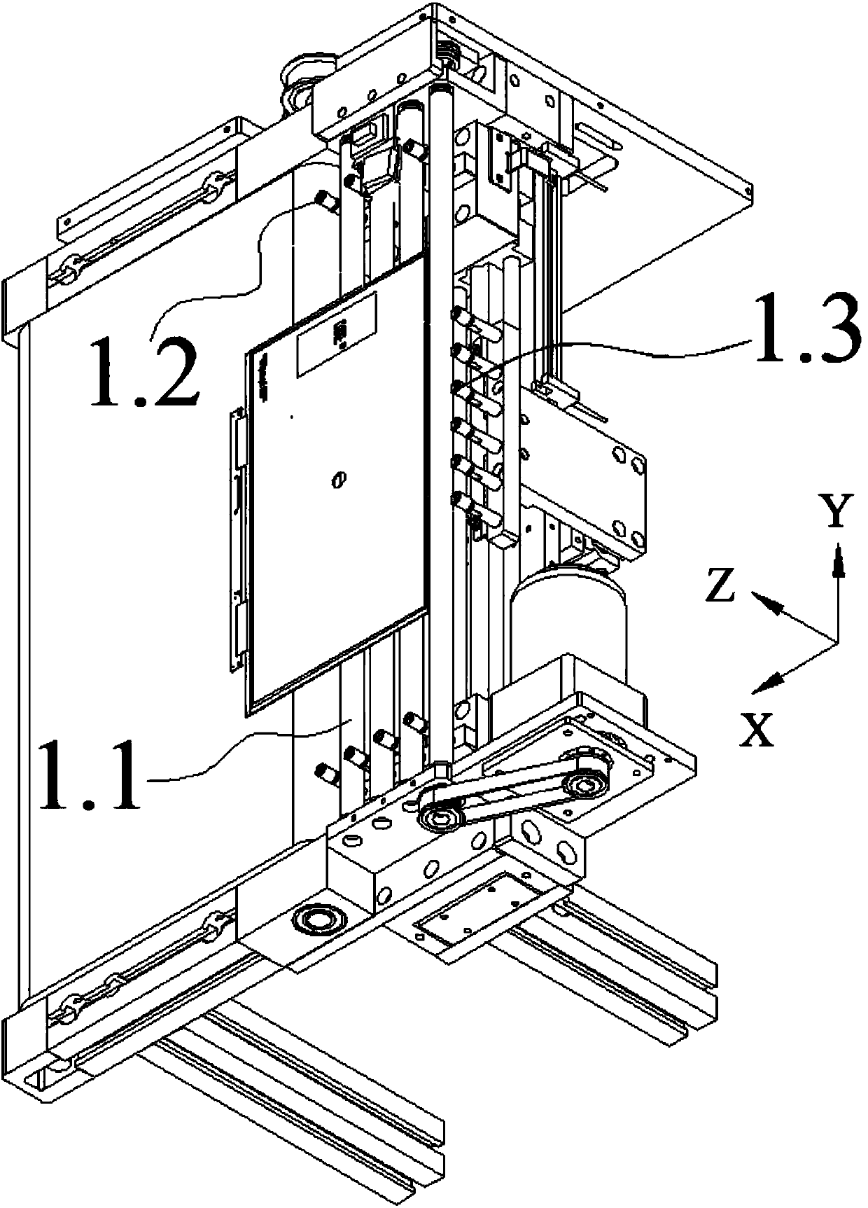
[0054] Such as Figure 3-4 As shown, a feeding device 1 is arranged in front of the sheet distributing device 3, and the feeding device 1 includes a feeding belt at an upstream end and a positioning device at a downstream end. The feeding belt is arranged along the X direction, and its discharging end is connected with the positioning device. The leaning device includes a first roller set 1.1, a second roller set 1.2 and a third roller set 1.3. The first roller set 1.1 engages with the feeding belt an...


PUM


Abstract

The invention relates to the technical field of panel optical detection devices, in particular to a panel detection device. It includes a base, and it is characterized in that: the base is sequentially arranged along the conveying direction of the panel, and a dispatching device is used to carry the panel to be detected to be transferred to the detection platform of the automatic optical detection device; the automatic optical detection device uses It is used for optical inspection of the panels to be inspected on the inspection platform; the discharge device is used to transport the panels that are detected as finished products by the automatic optical inspection device; the storage device is used to store the panels that are identified as NG products by the automatic optical inspection device . The panel detection device of the present invention has reasonable structural layout, high panel detection efficiency, greatly improved panel detection efficiency, and has great popularization value.

Description

technical field [0001] The invention relates to the technical field of panel optical detection devices, in particular to a panel detection device. Background technique [0002] AOI (Automatic Optic Inspection) is a technology based on optical principles to detect common defects encountered in manufacturing. In the liquid crystal panel manufacturing industry, AOI equipment can be used to detect Panel (panel). During detection, the display panel is first placed on the detection airborne platform for alignment. After the alignment is completed, the image capture unit collects image information on the display panel along the X-axis or Y-axis of the display panel. Image processing is performed on the photo, and then image segmentation is performed on the processed image to separate the target. Then compare the target with the defect parameters (Defect Spec) (including Size (size), Length (length), Contrast (contrast), SEMU (Semu indicator) and so on. Objects that meet the defe...

Claims


Application Information

Patent Timeline
Patent Type & Authority Applications(China)
IPC IPC(8): B65G47/90
CPCB65G47/901
Inventor 朱涛叶坤商秋锋
Owner KUSN JINGXUN ELECTRONICS TECH
Why Eureka
Try Eureka