Microscopic optical system for arc circumference defect detection

A defect detection and optical system technology, applied in the field of micro-optical systems, can solve problems such as effect and efficiency discount

Pending Publication Date: 2021-09-03
BEIJING C&W ELECTRONICS GRP
View PDF0 Cites 0 Cited by
  • Summary
  • Abstract
  • Description
  • Claims
  • Application Information

AI Technical Summary

Problems solved by technology

In this method, the size and position of the inspection area are different in the imaging, and even invalid images may appear due to the slight difference in the product placement position, and the effect and efficiency of defect detection are greatly reduced.

Method used


Image

  • Microscopic optical system for arc circumference defect detection
  • Microscopic optical system for arc circumference defect detection
  • Microscopic optical system for arc circumference defect detection

Examples


Embodiment 1

[0043] On the basis of the above structure, this embodiment also includes a platform on which the drive unit is fixedly installed.

[0044]The above-mentioned driving unit can be a motor, which is fixedly installed on the platform through bolts, and its driving end is vertically upward, and is fixedly connected with the center of the lower surface of the horizontally arranged rotating disk. During detection, the product 4 is directly placed on the rotating disk, and the motor drives the rotating disk and the product 4 to rotate, so that the product 4 makes a circular motion, so that the infinite imaging unit can fully capture the image of the product 4.

[0045] In addition to the implementation mode, during the detection process, the product 4 to be detected can also be directly placed on the platform, and it is stationary relative to the platform; at this time, the drive unit is fixed and erected on the platform through a bracket, and is used to drive the imaging rotation uni...

Embodiment 2

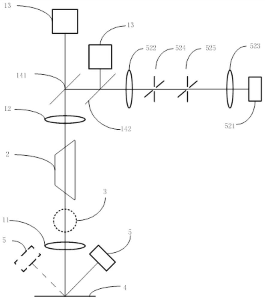
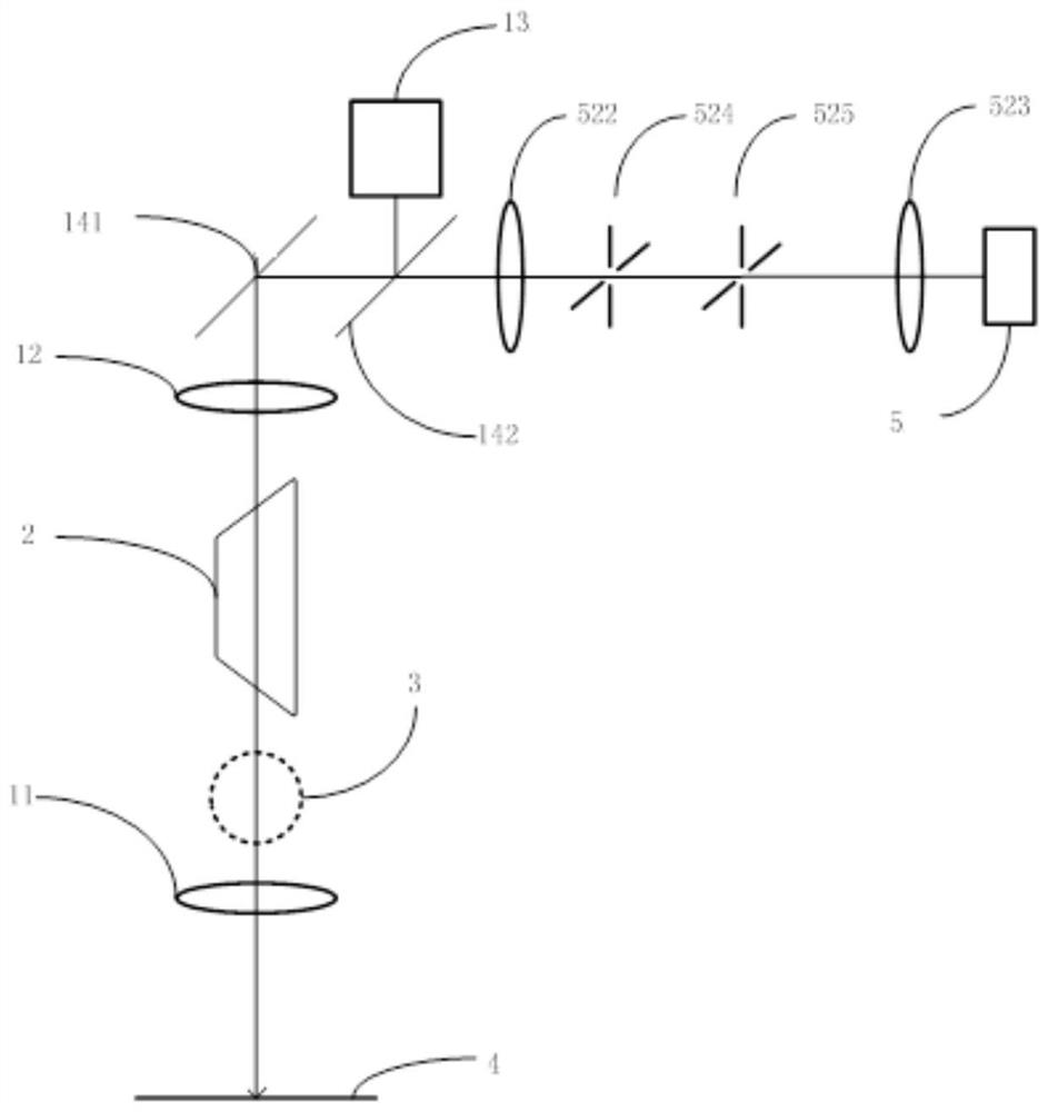
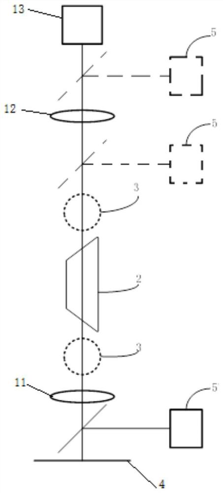
[0049] On the basis of the above structure, in this embodiment, the infinity imaging unit includes an infinity microscopic objective lens 11 and an imaging device, and the infinity microscopic objective lens 11 and the imaging device are erected above the drive unit at intervals from bottom to top. The micro-objective lens 11 is used to form the light generated by the product 4 into parallel light, which is then imaged by the imaging device; the imaging rotation unit is located between the infinity micro-objective lens 11 and the imaging device. During the detection process, the light generated by the product 4 passes through the infinity microscope objective lens 11 to form parallel light, and then is imaged by the imaging device. The imaging effect is better, so as to improve the effect of product 4 defect detection.

[0050] During detection, the above-mentioned imaging device is fixedly set, and the infinity microscopic objective lens 11 can be fixedly set, and this detecti...

Embodiment 3

[0052] On the basis of Embodiment 2, in this embodiment, the infinity imaging unit further includes an autofocus device 3 , which is fixed and used to drive the infinity microscope objective lens 11 to move up and down. During the detection process, the infinity microscope objective lens 11 is driven to move up and down by the autofocus device 3 to meet the imaging requirements of different products 4 and has a wider application range.

[0053] What above-mentioned autofocus device 3 adopted is the autofocus system in the prior art, and its specific structure and principle are not repeated here, and it is fixedly erected on the top of the platform by a bracket; It is fixedly installed on the autofocus system, and the position of the infinity microscopic objective 11 is adjusted up and down by the autofocus system, so as to adjust the distance between the infinity microscopic objective 11 and the imaging device, so as to meet the detection requirements of different products 4 . ...


PUM


Abstract

The invention relates to a microscopic optical system for arc circumference defect detection, and the system comprises a driving unit, an imaging rotation unit and an infinite imaging unit; the driving unit is fixedly arranged and is used for driving a product to be detected to horizontally rotate around a vertically arranged shaft, and the imaging rotation unit and the infinite imaging unit are erected above the driving unit; the infinite imaging unit is used for imaging a product, and the imaging rotating unit is used for rotating an image when the product is imaged. The invention has the beneficial effects that hole area arc circumference defect detection is realized, meanwhile, the defects that the position size of a detection area and a repeated area are not fixed when an arc target is collected in a rectangular visual field are overcome, the optical detection efficiency is greatly improved, the detection is more comprehensive, and the detection effect is better.

Description

technical field [0001] The invention relates to the technical field of surface defect detection, in particular to a microscopic optical system for arc circumference defect detection. Background technique [0002] OLED-Organic Light-Emitting Diode (OLED-Organic Light-Emitting Diode) display technology represented by flexible displays is becoming more and more common, most notably in products such as mobile phones, media players and small entry-level TVs. In order to meet the higher requirements, the full screen came into being. Various front functions such as the front camera flash or speakers have to enter the display area, so a full-screen hole-digging technology appears. Peripheral quality affects the pixel display around the hole. Once tiny cracks or other defects appear, it is only a matter of time before a wider range of bright and dark defects appear. Therefore, a full screen must detect sub-micron defects in the hole area, but the hole area will have a complete or p...

Claims


Application Information

Patent Timeline
Patent Type & Authority Applications(China)
IPC IPC(8): G01N21/89G01N21/892G02B21/36
CPCG01N21/8901G01N21/892G02B21/361
Inventor 王馨莹李伟刘欣孟鹏飞王福旺李立锋宋思儒林涛陶平田永军
Owner BEIJING C&W ELECTRONICS GRP
Why Eureka
Try Eureka