Optical detection device and optical detection method

A technology of optical detection and light beam, which is applied in the field of optical detection and can solve the problems of long time consumption

Active Publication Date: 2020-04-07
SHANGHAI YUWEI SEMICON TECH CO LTD
View PDF7 Cites 0 Cited by
  • Summary
  • Abstract
  • Description
  • Claims
  • Application Information

AI Technical Summary

Problems solved by technology

Existing AOI equipment can only acquire a clear image of one height surface at a time. To realize the detection of different heights of the surface to be tested, multiple image acquisitions are required, which takes a long time

Method used


Image

  • Optical detection device and optical detection method
  • Optical detection device and optical detection method
  • Optical detection device and optical detection method

Examples


Embodiment Construction

[0040] The present invention will be further described in detail below in conjunction with the accompanying drawings and embodiments. It should be understood that the specific embodiments described here are only used to explain the present invention, but not to limit the present invention. In addition, it should be noted that, for the convenience of description, only some structures related to the present invention are shown in the drawings but not all structures.

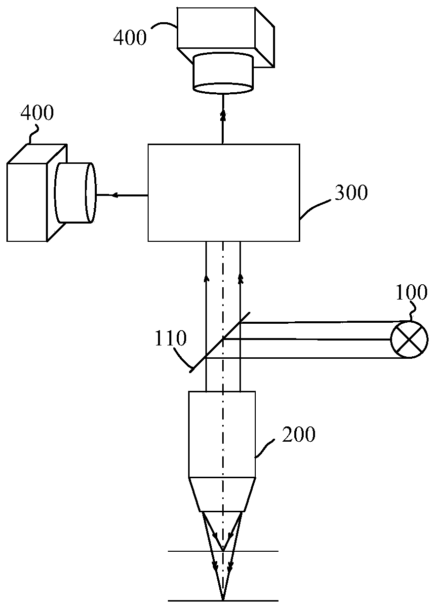
[0041] figure 1 It is a schematic structural diagram of an optical detection device provided by an embodiment of the present invention, refer to figure 1, the optical detection device includes: a light source 100, used to emit a detection beam; a chromatic aberration objective lens 200, located on the optical path of the detection beam, mainly used to collect the light beam reflected and / or scattered by at least two surfaces of the object to be measured and emit it The signal beam, in this embodiment, the chromat...


PUM


Abstract

Embodiments of the invention disclose an optical detection device and an optical detection method. The optical detection device comprises a light source, a chromatic aberration objective lens, a multi-wavelength separation unit and at least two detectors, wherein the light source is used for emitting detection light beams; the chromatic aberration objective lens is used for collecting light beamsreflected and / or scattered by at least two surfaces of a to-be-detected object and emitting signal light beams; at least two light beams with different central wavelengths in the detection light beamsare respectively and correspondingly focused on the at least two surfaces; the multi-wavelength separation unit is used for separating at least two sub-signal light beams with different central wavelengths from the signal light beams; and the at least two detectors are used for respectively receiving the at least two sub-signal light beams with different central wavelengths and respectively obtaining image information of the at least two surfaces of the to-be-detected object according to the at least two sub-signal light beams with different central wavelengths. The optical detection device and the optical detection method are capable of solving the problem that the to-be-detected objects with fluctuant surfaces need multiple times of image acquisition, and shortening the optical detection time and improving the detection efficiency.

Description

technical field [0001] Embodiments of the present invention relate to the technical field of optical detection, and in particular, to an optical detection device and an optical detection method. Background technique [0002] With the deepening and popularization of industrial automation and intelligence, the use of automatic optical inspection equipment (Auto Optical Inspection, AOI) to replace traditional manual visual inspection has become a technological development trend. AOI equipment is widely used in automobiles, medicine, transportation, semiconductors and other fields due to its fast and accurate defect identification and positioning capabilities. [0003] At present, existing AOI equipment usually includes an optical imaging system, an object stage, a material transfer system, and the like. The optical imaging system includes an illumination unit, an imaging objective lens, and a detector. In order to obtain a clear image of the surface of the object to be tested...

Claims


Application Information

Patent Timeline
Patent Type & Authority Patents(China)
IPC IPC(8): G01N21/88G01N21/01
CPCG01N21/01G01N21/88G01N21/8851G01N2021/0112
Inventor 于凯航
Owner SHANGHAI YUWEI SEMICON TECH CO LTD
Why Eureka
Try Eureka