Ultrasonic sensor having acoustic matching member with conductive layer formed on and extending only along acoustic matching member connecting surface

a technology of ultrasonic sensors and matching members, applied in the direction of generators/motors, instruments, using reradiation, etc., can solve the problems of reducing detection efficiency, noise generation, attenuation of vibration, etc., and achieves the effect of enhancing the detection efficiency of ultrasonic sensors, reducing noise generation, and easy bonding

Inactive Publication Date: 2010-04-13
DENSO CORP
View PDF20 Cites 17 Cited by
  • Summary
  • Abstract
  • Description
  • Claims
  • Application Information

AI Technical Summary

Benefits of technology

[0009]The present invention has been made in view of the above-mentioned problem, and an object of the present invention is to provide an improved ultrasonic sensor having an acoustic matching member, in which high detection efficiency is realized. Another object of the present invention is to provide a method of manufacturing such an ultrasonic sensor.
[0011]The piezoelectric element is sandwiched with a pair of electrodes and connected to the acoustic matching member via a conductive layer formed on the acoustic matching member. The piezoelectric element, the acoustic matching member and the processing circuit are contained in a casing. A vibration-attenuating member is disposed between side surfaces of the acoustic matching member and an inner wall of the casing to suppress vibration transmission between the casing and the acoustic matching member.
[0013]Since the overhang area is formed on the conductive layer, the wire connecting the first electrode to the processing circuit is easily bonded on the conductive layer. The connecting surface of the acoustic matching member is larger than the area of the piezoelectric element connected to the acoustic matching member, and an entire area of the piezoelectric element is connected to the acoustic matching member. Therefore, no vibrations in different phases are generated in the acoustic matching member, and generation of noises is suppressed. Accordingly, ultrasonic vibrations received by the acoustic matching member are effectively transmitted to the piezoelectric element, thereby enhancing detection efficiency of the ultrasonic sensor.
[0014]The conductive layer formed on the connecting surface of the acoustic matching member may be extended to its side surface to bond a wire thereon for electrically connecting the conductive layer to the processing circuit. In this case the overhang area may be eliminated. A wiring element may be formed on an inner surface of the casing for easily making an electrically connection between the conductive layer and the processing circuit. Alternatively, the casing and the vibration-attenuating member may be made of a conductive material to simplify the electrical connection between the conductive layer and the processing circuit.
[0015]Plural combined units, each unit consisting of a piezoelectric element and an acoustic matching member, may be arranged in an array. A block for forming plural piezoelectric elements and another block for forming plural acoustic members are connected, and then the combined blocks are diced into individual combined units. In this manner, the plural combined units are easily manufactured.
[0016]According to the present invention, the electrical connection in the ultrasonic sensor is easily made and the detection sensitivity is enhanced. Other objects and features of the present invention will become more readily apparent from a better understanding of the preferred embodiments described below with reference to the following drawings.

Problems solved by technology

The non-connected portion of the piezoelectric element vibrates in a phase different from that of the connected portion, generating noises or causing attenuation of vibration.
This results in decrease in detection efficiency.
The slanted connection and / or the boundary may cause attenuation of vibration and decrease in a connecting force between the piezoelectric element and the acoustic matching layer.

Method used


Image

  • Ultrasonic sensor having acoustic matching member with conductive layer formed on and extending only along acoustic matching member connecting surface
  • Ultrasonic sensor having acoustic matching member with conductive layer formed on and extending only along acoustic matching member connecting surface
  • Ultrasonic sensor having acoustic matching member with conductive layer formed on and extending only along acoustic matching member connecting surface

Examples


first embodiment

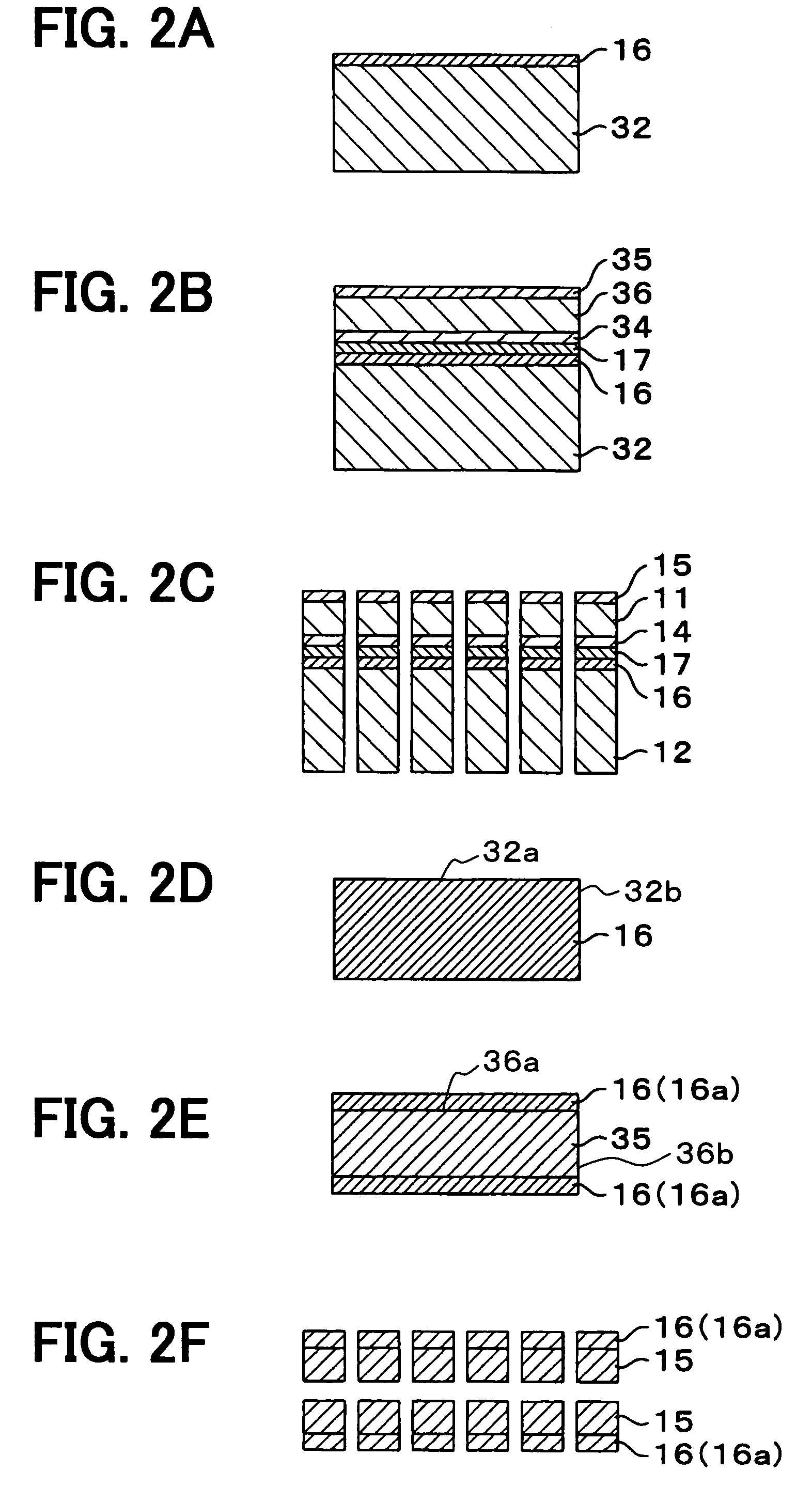
[0027]the present invention will be described with reference to FIGS. 1A-3. The ultrasonic sensor according to the present invention is advantageously used in an automotive vehicle. The embodiment described here is an ultrasonic sensor for use in an automotive vehicle. Ultrasonic waves are transmitted from an on-board transmitter, and the ultrasonic waves reflected on an object to be detected (e.g., an obstacle in front of the vehicle) are received by the ultrasonic sensor, thereby detecting a distance from the vehicle and / or positions of the object.

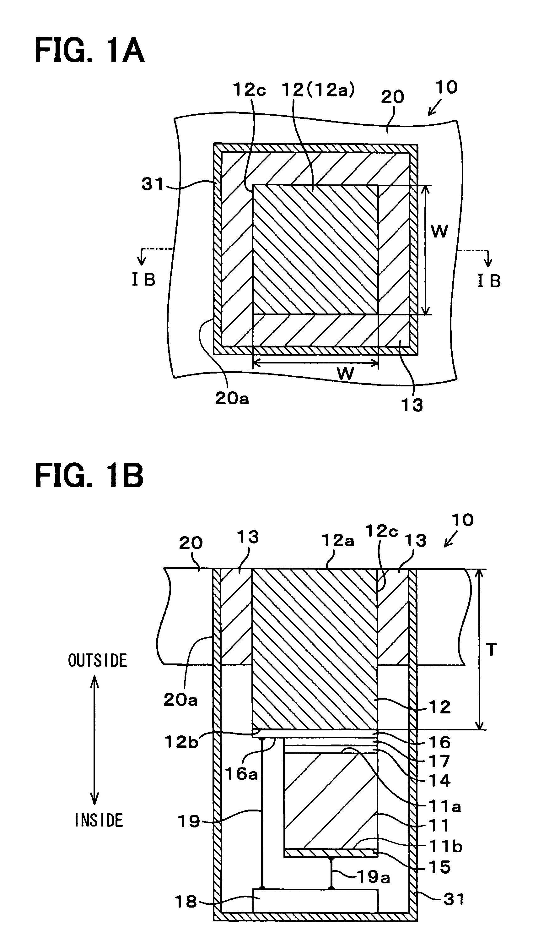
[0028]First, referring to FIGS. 1A and 1B, a structure of the ultrasonic sensor 10 will be described. The ultrasonic sensor 10 includes a piezoelectric element 11 that converts ultrasonic vibrations to electrical signals, an acoustic matching member 12 that receives the ultrasonic waves and transfers ultrasonic vibrations to the piezoelectric element 11, and a processing circuit 18 that processes the output signals of the piezoelectric e...

second embodiment

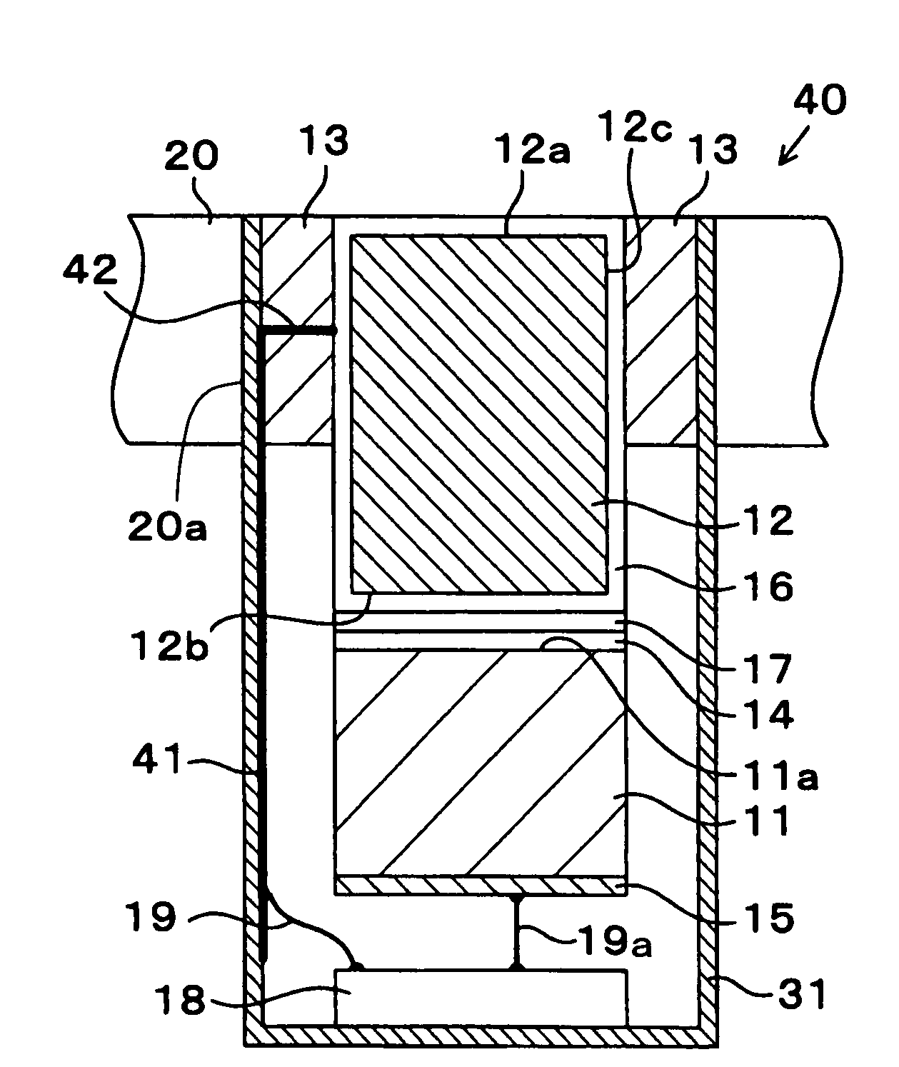
[0052]An ultrasonic sensor 40 as the present invention will be described with reference to FIG. 4. In this embodiment, the conductive layer 16 formed on the connecting surface 12b is extended to cover an entire surface of the acoustic matching member 12. It is also possible to extend the conductive layer 16 to partially cover its side surface 12c. The conductive layer 16 is formed as a thin film not to hinder vibration of the acoustic matching member 12. The connecting surface 12b is made to have the substantially the same area as the first surface 11a of the piezoelectric element 11. It is possible, however, to make the connecting surface 12b larger than the first surface 11a of the piezoelectric element 11.

[0053]The first electrode 14 is connected to the conductive layer 16 with the conductive adhesive 17 in the same manner as in the first embodiment. In the second embodiment, the wire 19 is bonded to the conductive layer 16 formed on the side surface 12c of the acoustic matching ...

third embodiment

[0056]An ultrasonic sensor 50 as the present invention will be described with reference to FIGS. 6A and 6B. In this embodiment, four pairs of combined units, each consisting of a piezoelectric element 11p-11s and an acoustic matching member 12p-12s, are arranged in an array. Three-dimensional detection of positions of an object is performed in this embodiment. Four combined units are contained in the casing 31 via the vibration-attenuating member 13, and electrically connected to the processing circuit 13 through wires 19, 19a. Not only a distance from the vehicle but also a position of the object can be detected based on phase differences among the combined units.

[0057]A width W (refer to FIG. 6A) of each acoustic matching element 12p-12s is made equal to or less than one half of a wavelength λa of the ultrasonic wave in air (W≦½λa), and a distance d (refer to FIG. 6A) between the combined units is made equal to one half of the wavelength (d=½λa). Time differences among the combine...


PUM

PropertyMeasurementUnit
thicknessaaaaaaaaaa
widthaaaaaaaaaa
frequencyaaaaaaaaaa

Abstract

An ultrasonic sensor according to the present invention is used, for example, for detecting an obstacle positioned in front of an automotive vehicle. The ultrasonic sensor includes an piezoelectric element connected to an acoustic matching member and a processing circuit, all contained in a casing. Ultrasonic waves reflected on an object are received by the acoustic matching member and converted into electrical signals in the piezoelectric element. The electrical signals are processed in the processing circuit to thereby detect a distance to the object and / or positions of the object. A surface of the acoustic matching member connected to the piezoelectric element is made larger than the piezoelectric element to form an overhang area on a conductive layer formed on the acoustic matching member. In this manner, electrical connection in the ultrasonic sensor is easily made, and detection sensitivity of the ultrasonic sensor is enhanced.

Description

CROSS-REFERENCE TO RELATED APPLICATION[0001]This application is based upon and claims benefit of priority of Japanese Patent Application No. 2007-18027 filed on Jan. 29, 2007, the content of which is incorporated herein by reference.BACKGROUND OF THE INVENTION[0002]1. Field of the Invention[0003]The present invention relates to an ultrasonic sensor having a piezoelectric element connected to an acoustic matching member.[0004]2. Description of Related Art[0005]An ultrasonic sensor having a piezoelectric element mounted on a substrate such as a metallic or resin substrate has been known hitherto. The ultrasonic sensor receives ultrasonic waves transmitted from a transmitter and reflected on an object to be detected. Based on signals outputted from the ultrasonic sensor, a position and / or a distance of the object is detected in a two- or tree-dimensional manner.[0006]Some of the ultrasonic sensors include an acoustic matching layer or a member for adjusting acoustic impedance and for i...

Claims


Application Information

Patent Timeline
Patent Type & Authority Patents(United States)
IPC IPC(8): H01L41/08G01S15/931H04R17/00H04R31/00
CPCG01S7/521G01S7/526G01S15/931G10K11/02G10K11/002Y10T29/42G01S2015/939
Inventor SUGIURA, MAKIKOOKUDA, YASUYUKI
Owner DENSO CORP
Why Eureka
Try Eureka