Simple oil separator for automobile air conditioner system

An automobile air-conditioning system and oil separator technology, applied in the field of automobile air-conditioning, can solve the problems of low strength, easy to break, thin capillary, etc., and achieve the effect of fewer components, simple structure, and small volume

Pending Publication Date: 2018-05-18
TIANJIN SANDEN AUTO AIR CONDITIONING
View PDF0 Cites 1 Cited by
  • Summary
  • Abstract
  • Description
  • Claims
  • Application Information

AI Technical Summary

Problems solved by technology

The disadvantage is that the capillary is thinner and less strong, and it is prone to breakage under the vibration caused by the car engine

Method used


Image

  • Simple oil separator for automobile air conditioner system
  • Simple oil separator for automobile air conditioner system
  • Simple oil separator for automobile air conditioner system

Examples


Embodiment 1

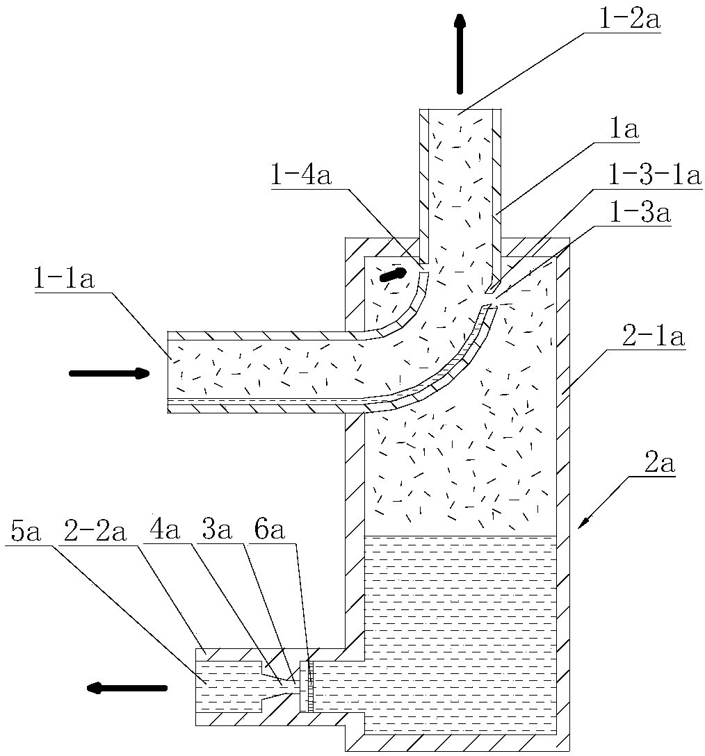
[0031] See figure 1 , a simple oil separator for automobile air conditioning system, including oil distribution elbow 1a, oil storage cavity 2a. The oil distribution elbow is composed of two straight pipe sections and an arc-shaped elbow section connecting the two straight pipe sections. The oil storage chamber is composed of a cylindrical or square column main body part 2-1a arranged upright and an oil return output extension part 2-2a arranged on one side of the main body part of the chamber near the bottom. The oil distribution elbow is worn and fixed on the upper part of the oil storage cavity with both ends exposed. The installation direction of the oil distribution elbow is preferably: the plane where it is located and the horizontal plane are within the range of 45° to 90°, preferably 90° °. One end of the oil distribution elbow is the refrigerant inlet port, and the other end is the refrigerant outlet port. Considering the ease of installation and connection and the...

Embodiment 2

[0041] See figure 2 , the difference between this embodiment and embodiment one is:

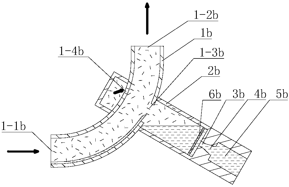
[0042] The oil distribution elbow 1b is composed of an arc-shaped elbow, the oil storage chamber 2b is a thin straight tube arranged obliquely, the oil distribution port 1-3b is opened on the arc surface of the side with a larger curvature radius, and the air return port 1-4b The oil return structure formed by the orifice 3b, the oil discharge hole 4b and the oil return port 5b is set directly on the lower end of the oil storage cavity.

[0043] In addition to the above-mentioned features different from Embodiment 1, other structures, such as the arrangement of the refrigerant inlet port 1-1b and the refrigerant outlet port 1-2b, the preferred shape of the oil distribution port, the preferred shape and size parameters of the orifice, the filter screen The settings and the like are the same as those in Embodiment 1, and will not be repeated here.

Embodiment 3

[0045] See image 3 , the difference between this embodiment and embodiment one is:

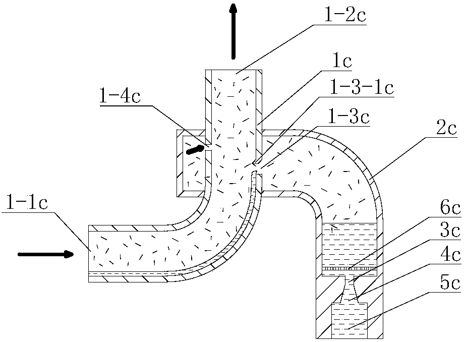
[0046] The oil storage chamber 2c adopts a thin elbow structure composed of two straight pipe sections and an arc-shaped elbow section connecting the two straight pipe sections, and an oil return structure composed of an orifice 3c, an oil discharge hole 4c and an oil return port 5c Set in the lower straight pipe section.

[0047] In addition to the above-mentioned features different from Embodiment 1, other structures, such as the shape of the oil distribution elbow 1c, the location of the oil distribution port 1-3c, the location of the return air port 1-4c, the refrigerant inlet port 1-1c and the refrigerant The setting of the outlet port 1-2c, the preferred shape of the oil distribution port, the preferred shape and size parameters of the orifice, the setting of the filter screen, the setting of the oil retaining flange 1-3-1c on the oil distribution port, etc. are all the same as in the ...


PUM


Abstract

The invention relates to a simple oil separator for an automobile air conditioner system. The simple oil separator comprises an oil separation bent pipe and an oil storage cavity. The oil separation bent pipe penetrates through and is fixed to the upper portion of the oil storage cavity in the mode that the two ends are exposed, the two ends of the oil separation bent pipe are a refrigerant inletend and a refrigerant outlet end, the arc face on the side with the large curvature radius of the oil separation bent pipe or a straight pipe section connected with the tail end of the arc face on theside is provided with an oil separation port, and the oil separation port is located in the oil storage cavity. The lower end of the oil storage cavity is provided with an oil return mechanism. In the oil output direction, the oil return mechanism is formed by sequentially connecting a throttling hole, an oil drainage hole and an oil return port. The oil drainage hole is a variable-section hole with the cross section increased gradually. According to the simple oil separator, in the flowing process of gas state refrigerant and liquid state refrigerating machine oil in the oil separation bentpipe, oil separation is achieved under the effect of weight and inertia. Oil enters the oil storage cavity through an oil separation port and returns back into a compressor of the air conditioner system through the oil return structure. The simple oil separator has the advantages of being small in size, simple in structure and resistant to vibration.

Description

technical field [0001] The invention belongs to the technical field of automobile air-conditioning, in particular to a simple oil separator used in an automobile air-conditioning system. Background technique [0002] In the automobile air-conditioning system, the oil content in the refrigerant has a great influence on the heat exchange capacity of the air conditioner. The test results show that when the oil content is 3%, the heat transfer capacity decreases by about 2%; when the oil content is 10%, the heat transfer capacity decreases by about 16%; when the oil content is 15%, the heat transfer capacity decreases by about 28%. At present, when the oil separator is installed in the automotive air-conditioning system, the oil content is about 10%, which greatly reduces the heat exchange capacity; after the oil separator is installed, the oil content can be guaranteed to be lower than 3%, which can make the The heat exchange capacity of the air conditioner drops by less than ...

Claims


Application Information

Patent Timeline
Patent Type & Authority Applications(China)
IPC IPC(8): F25B43/02
CPCF25B43/02F25B2400/23
Inventor 沈兆昆陆新林何威郝永健
Owner TIANJIN SANDEN AUTO AIR CONDITIONING
Why Eureka
Try Eureka