Intelligent drying device for medical device parts

A technology of drying device and mechanical accessories, applied in the field of medical machinery, can solve the problems of incapable of rational distribution and classification of medical machinery accessories, uneven drying speed, etc., achieve scientific and reasonable design structure, improve drying speed, and improve work efficiency. The effect of efficiency

Inactive Publication Date: 2018-05-18
宁波杨古诚文化传播有限公司
View PDF2 Cites 0 Cited by
  • Summary
  • Abstract
  • Description
  • Claims
  • Application Information

AI Technical Summary

Problems solved by technology

[0003] The existing intelligent drying device for medical machinery parts loves you. When people use it, there is a problem that they cannot reasonably classify different types of medical machinery parts, and the speed of drying when they are stacked together is not fast. For this reason We propose an intelligent drying device for medical machinery parts

Method used


Image

  • Intelligent drying device for medical device parts
  • Intelligent drying device for medical device parts
  • Intelligent drying device for medical device parts

Examples


Embodiment 1

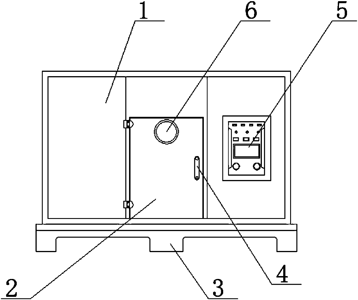
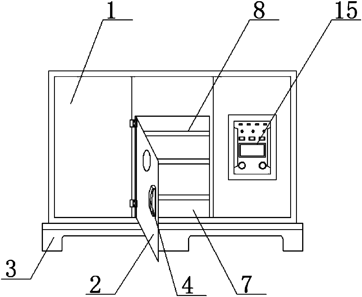
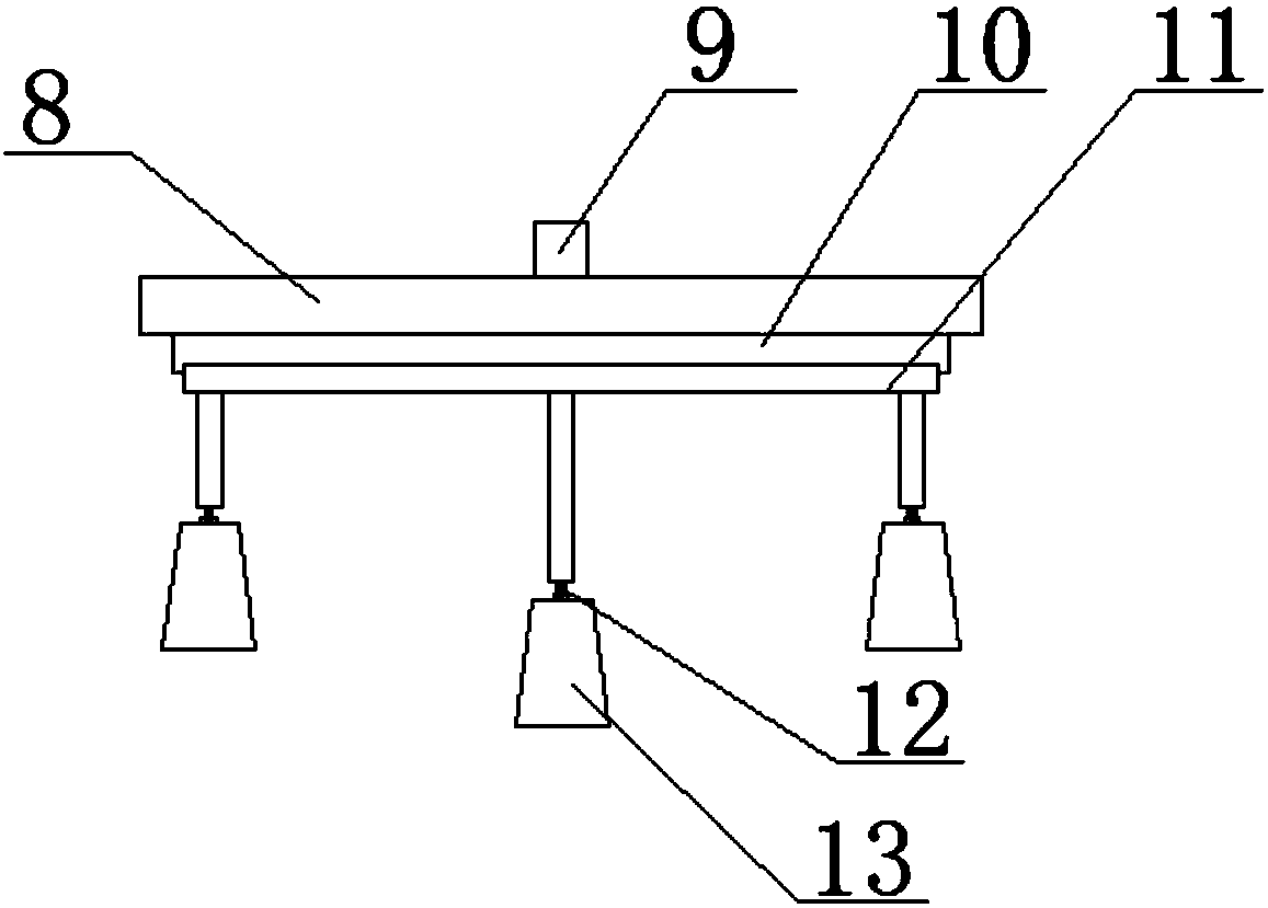
[0020] see figure 1 , figure 2 , image 3 , Figure 4 and Figure 5 , the present invention provides a technical solution: an intelligent drying device for medical machinery accessories, including an outer casing 1, a revolving door 2 is arranged in the middle of the surface of the outer casing 1, and the revolving door 2 and the outer casing 1 are rotatably connected by a hinge. An observation window 6 is arranged above the surface of the revolving door 2, a handle 4 is fixedly arranged on one side of the surface of the revolving door 2 by welding, a switch 5 is arranged on one side of the surface of the outer casing 1, and the outer casing 1 and the switch 5 are fixedly connected by welding, The bottom of the outer casing 1 is fixedly provided with a base 3 by welding, the inside of the outer casing 1 is provided with a drying chamber 7, the inside of the drying chamber 7 is provided with a fixing plate 8, and the drying chamber 7 and the fixing plate 8 are fixedly conne...

Embodiment 2

[0026] see figure 1 , figure 2 , Figure 4 , Figure 5 and Figure 6 , the present invention provides a technical solution: an intelligent drying device for medical machinery accessories, including an outer casing 1, a revolving door 2 is arranged in the middle of the surface of the outer casing 1, and the revolving door 2 and the outer casing 1 are rotatably connected by a hinge. An observation window 6 is arranged above the surface of the revolving door 2, a handle 4 is fixedly arranged on one side of the surface of the revolving door 2 by welding, a switch 5 is arranged on one side of the surface of the outer casing 1, and the outer casing 1 and the switch 5 are fixedly connected by welding, The bottom of the outer casing 1 is fixedly provided with a base 3 by welding, the inside of the outer casing 1 is provided with a drying chamber 7, the inside of the drying chamber 7 is provided with a fixing plate 8, and the drying chamber 7 and the fixing plate 8 are fixedly conn...


PUM


Abstract

The invention discloses an intelligent drying device for medical device parts. The intelligent drying device comprises an outer shell. A swing door is arranged in the middle of the surface of the outer shell and is rotationally connected with the outer shell through a hinge. An observation window is arranged on the upper portion of the surface of the swing door. A pull handle is fixedly arranged on one side of the surface of the swing door through welding. A switch is arranged on one side of the surface of the outer shell. The outer shell is fixedly connected with the switch through welding. Abase is fixedly arranged at the bottom of the outer shell through welding. The intelligent drying device is practical design is scientific and reasonable in structure, safe and convenient to use, a rotary disc is arranged in a drying chamber of the intelligent drying device, a plurality of hooks are further arranged under the rotary disc, a plurality of storage boxes are hung on the hooks, medical devices needing to be dried can be put into the storage boxes after sorted and are driven by the rotary disc to rotate, thus the drying speed is higher, and the storage boxes are designed to be of aporous net structure.

Description

technical field [0001] The invention belongs to the technical field of medical machinery, and in particular relates to an intelligent drying device for medical machinery accessories. Background technique [0002] The full English name of drying equipment is Drying equipment, which refers to a combination of a series of mechanical equipment that dries moisture or other liquids on the surface of objects through certain technical means. The current popular drying technologies are mainly ultraviolet drying, infrared drying, electromagnetic drying and hot air drying. They have their own characteristics and are widely used in the drying of various mechanical equipment and food. [0003] The existing intelligent drying device for medical machinery parts loves you. When people use it, there is a problem that they cannot reasonably classify different types of medical machinery parts, and the speed of drying when they are piled up together is not fast. For this reason We propose an ...

Claims


Application Information

Patent Timeline
Patent Type & Authority Applications(China)
IPC IPC(8): F26B11/00F26B25/08
CPCF26B11/00F26B25/08
Inventor 杨桂山
Owner 宁波杨古诚文化传播有限公司
Why Eureka
Try Eureka