An optical system suitable for virtual reality equipment

An optical system and virtual reality technology, applied in the field of optical systems, can solve problems such as incompatibility, and achieve the effects of reducing processing costs, large field of view, and reducing chromatic aberration

Active Publication Date: 2020-04-03
SUZHOU UNIV OF SCI & TECH
View PDF7 Cites 0 Cited by
  • Summary
  • Abstract
  • Description
  • Claims
  • Application Information

AI Technical Summary

Problems solved by technology

[0006] The present invention aims at the deficiencies in existing virtual reality helmets that can only satisfy certain design indicators such as distortion or chromatic aberration, but cannot take into account all indicators, etc., and provides a helmet with good aberration correction, large field of view, and exit pupil diameter. and exit pupil distance, light and compact structure, suitable for optical systems of virtual reality equipment

Method used


Image

  • An optical system suitable for virtual reality equipment
  • An optical system suitable for virtual reality equipment
  • An optical system suitable for virtual reality equipment

Examples


Embodiment 1

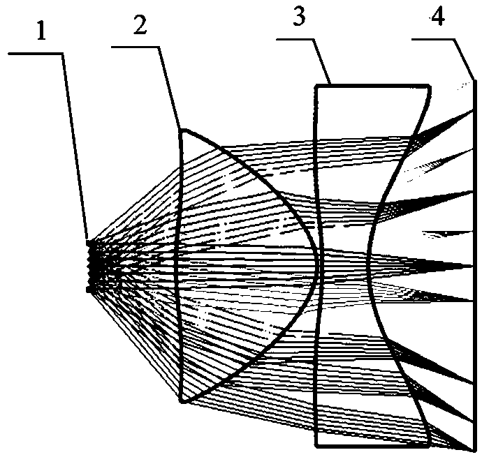
[0026] See attached figure 1 , is a schematic structural diagram of an optical system suitable for a virtual reality device provided in this embodiment. It includes a diaphragm 1, a positive power lens 2, a negative power lens 3 and a liquid crystal display 4 arranged in sequence along the optical axis. The light emitted by the liquid crystal display screen 4 sequentially passes through the negative power lens 3 and the positive power lens 2, and then enters the aperture 1, and then enters the pupil of the human eye. The two surfaces of the positive power lens 2 are aspheric surfaces, the surface opposite to the diaphragm is a convex surface, the surface opposite to the negative power lens 3 is concave, and both surfaces of the negative power lens 3 are concave aspherical surface. The optical system provided by this embodiment achieves the following optical properties:

[0027] (1) In this embodiment, the diagonal length of the liquid crystal display 4 is 5.5 inches, the re...

Embodiment 2

[0043] The structure of the optical system provided by this embodiment is as figure 1 As shown, it achieves the following optical properties:

[0044] (1) In this embodiment, the diagonal length of the liquid crystal display 4 is 5.5 inches, the resolution is 2560×1440, the number of pixels per inch (ppi, pixels per inch) is 538, and the pixel size is 47.25 μm, thus It can be calculated that the Nyquist frequency of the optical system is 10 line pairs / mm, and the field angle of the monocular diagonal of the optical system is 90 degrees.

[0045] (2) The focal power of lens 2 with positive refractive power is 0.05821mm -1 , the material is PMMA, the refractive index is 1.49, and the dispersion coefficient is 57.44; the focal power of the negative power lens 3 is -0.04821mm -1 , the material is POLYCARB, the refractive index is 1.58, and the dispersion coefficient is 29.9.

[0046] (3) The surface of lens 2 with positive dioptric power is a convex aspheric surface relative to...


PUM


Abstract

The invention discloses an optical system applicable to virtual reality equipment. The optical system applicable to the virtual reality equipment comprises a diaphragm, a positive focal power lens, anegative focal power lens and an image displayer in sequence in the optical axis direction; the positive focal power lens is used for inhibiting ray divergence angles which are incident from a big field angle, and the negative focal power lens is used for balancing astigmatism and distortion generated by the positive focal power lens. The two lenses are both made from a plastic material, the positive focal power lens is a low-refractive-index and high-dispersion-coefficient lens, the negative focal power lens is a high-refractive-index and low-dispersion-coefficient lens, and the combination of the two lenses can reduce chromatic aberration of the optical system. The optical system applicable to the virtual reality equipment is large in field angle, a single-eye diagonal field angle can reach 100 degrees, and thus good immersion sense is provided for the virtual reality equipment; good image quality and distortion are also obtained at an edge field lens set, and meanwhile, the lens sethas a large exit pupil distance and exit pupil aperture, which can provide more comfortable wearing experience for observers.

Description

technical field [0001] The invention relates to an optical system, in particular to an optical system suitable for virtual reality equipment. Background technique [0002] Virtual reality (Virtual Reality, VR) technology is a computer-generated, interactive and immersive visual virtual environment proposed in the 1980s. It can generate a variety of virtual environments according to needs, and is widely used in urban planning, areas such as driver training and interior design. In recent years, with the development of computer computing power and various types of sensors, various types of virtual reality helmets have appeared on the market. The basic structure is composed of a display screen or a mobile phone and a set of eyepieces. On the enlarged image, the sensor senses the changes of the human head and adjusts the images displayed in the left and right areas of the screen, so that the human eye can see a three-dimensional, interactive visual image. [0003] At present, t...

Claims


Application Information

Patent Timeline
Patent Type & Authority Patents(China)
IPC IPC(8): G02B27/01
CPCG02B27/0101G02B2027/011
Inventor 范君柳吴泉英陈宝华徐越
Owner SUZHOU UNIV OF SCI & TECH
Why Eureka
Try Eureka