A motor shock absorber

A technology of shock absorbing device and friction disc, applied in electromechanical devices, springs/shock absorbers, shock absorbers, etc., can solve problems such as shortening the service life of parts, easy loosening of shock absorbing pads, limited shock absorbing effect, etc. Ensure normal work, reduce vibration amplitude, and have obvious shock absorption effects

Inactive Publication Date: 2019-11-26
JIANGSU YUANHUA LIGHT CHEM EQUIP
View PDF6 Cites 0 Cited by
  • Summary
  • Abstract
  • Description
  • Claims
  • Application Information

AI Technical Summary

Problems solved by technology

[0002] As a device that converts electrical energy into mechanical energy, the motor is widely used as a driving mechanism in production and life. However, the motor is often accompanied by vibration and noise when it is working. The installation method of the existing motor is relatively simple. The rigid connector is directly fixed on the mounting base, so the shock absorption effect is very limited, and it will also cause the parts that use the motor to collide with each other under the long-term vibration of the motor, resulting in greater noise and reducing the service life of the parts
Loud noise deteriorates the production environment of the factory
The method of installing a shock absorber between the motor and the installation is also often used, but the shock absorber is easy to loosen and fall off, the shock absorption effect is limited, and the noise problem generated cannot be well overcome

Method used


Image

  • A motor shock absorber
  • A motor shock absorber
  • A motor shock absorber

Examples


Embodiment Construction

[0020] The specific implementation manners of the present invention will be described in further detail below in conjunction with the accompanying drawings.

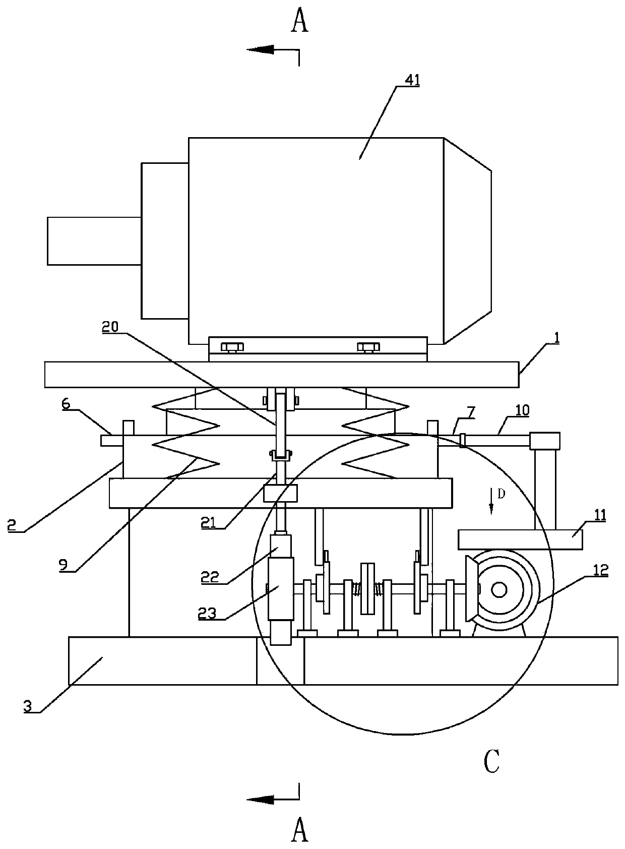
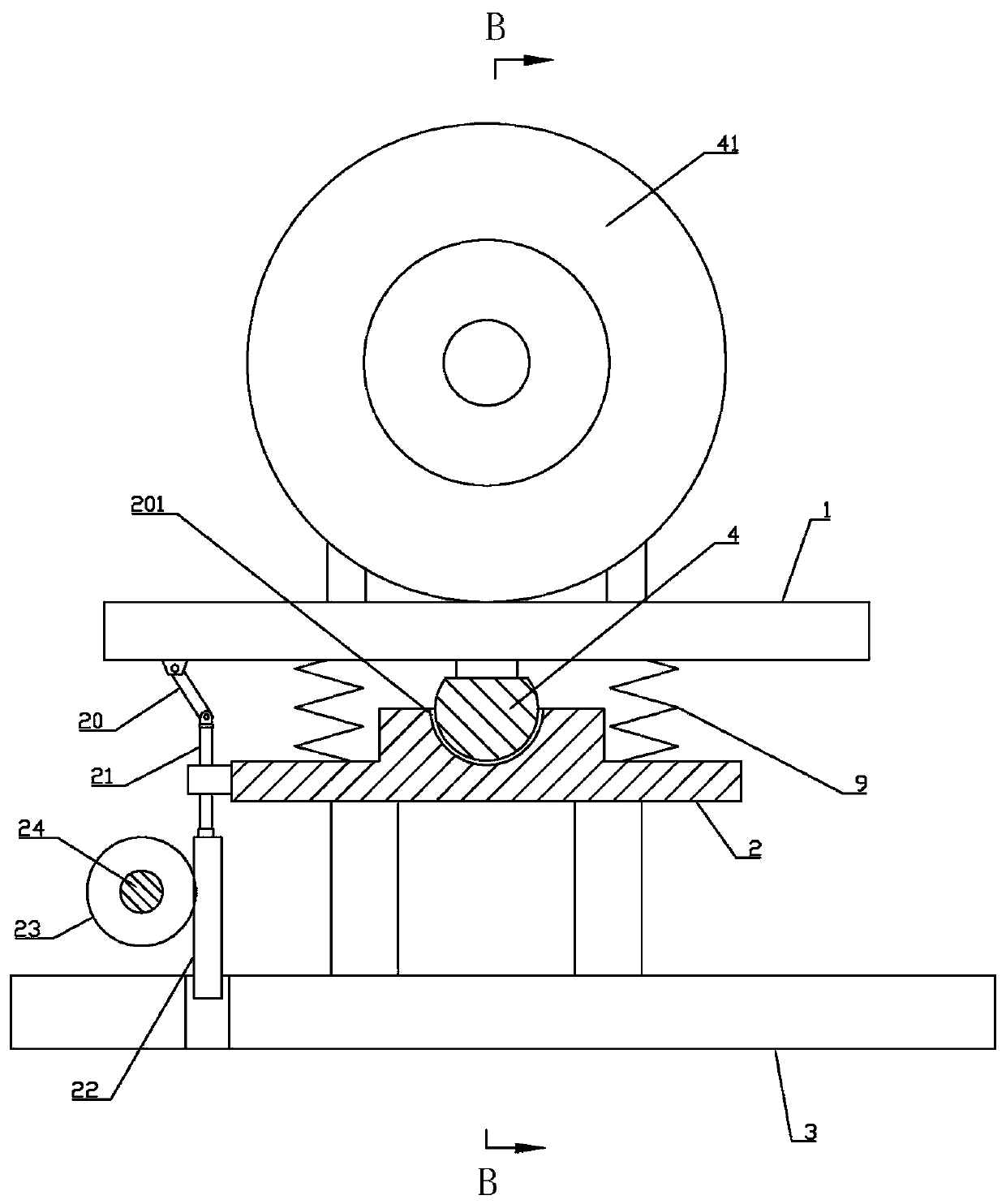
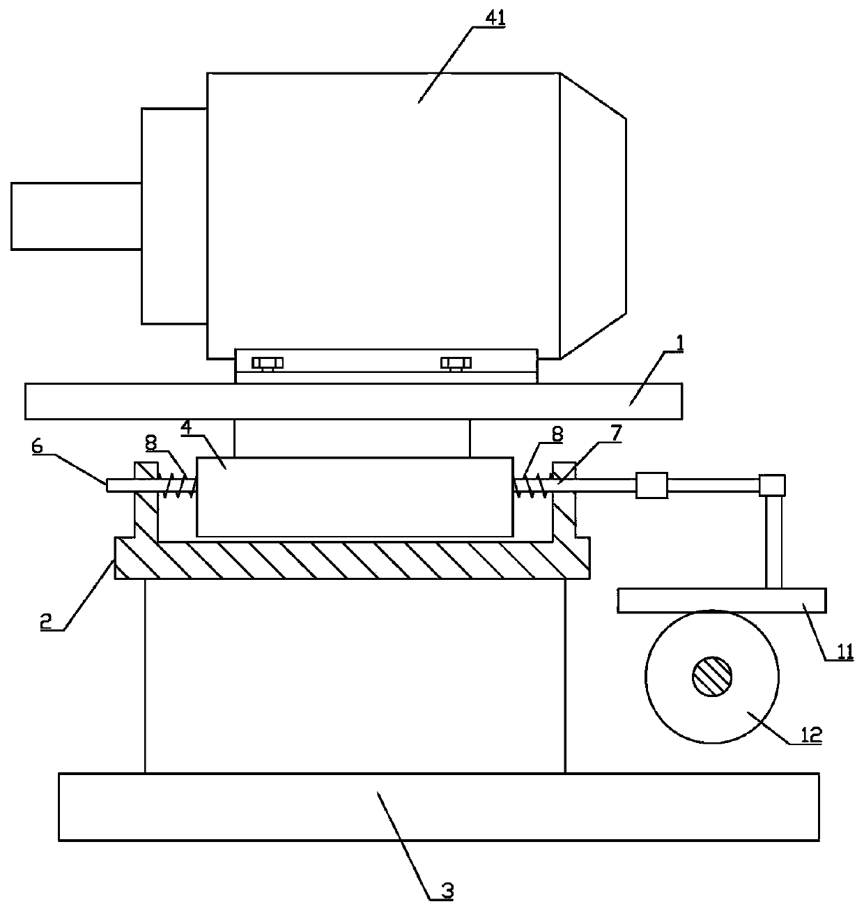
[0021] Depend on Figure 1 to Figure 7 Given, a motor damping device, including a fixed frame 1, a support base 2, a base 3, the support base 2 is fixed on the base 3, and the motor 41 is installed on the fixed frame 1, characterized in that the fixed frame 1 The bottom is fixed with a semi-cylindrical rotating body 4, the axis of the rotating body 4 is parallel to the axis of the motor output shaft, the upper part of the support base 2 is provided with a supporting arc 201 that cooperates with the rotating body 4, and the rotating body 4 is located in the supporting arc 201 The left end of the rotating body 4 is provided with a left guide rod 6 coaxial with it, and the right end is coaxially connected with a right guide rod 7. The ends of the left guide rod 6 and the right guide rod 7 away from the rotating body 4 pass ...


PUM


Abstract

Disclosed is a motor damping device. A half-cylinder-shaped rotator is fixedly installed at the bottom of a fixing frame. The end, stretching out of a supporting base, of a right guide rod is fixedlyconnected with a transmission frame, a first rack parallel to the axis of the rotator is fixedly arranged on the transmission frame, a first gear is meshed with the first rack, a driving bevel gear isinstalled on a first gear shaft and meshed with a driven bevel gear, the driven bevel gear is installed on a base through a bevel gear shaft and a bearing pedestal, the bevel gear shaft and a first friction disc shaft are connected so that power can only be transmitted to a first one-way transmission mechanism of the first friction disc shaft from the bevel gear shaft, and the first friction discshaft rotates so that the first friction disc and a second friction disc can rotate relatively. Due to relative rotation of the two friction discs, vibration is converted into friction heat to be consumed, the vibration amplitude is lowered, vibration of other parts is lowered, and the service life of the parts is prolonged. Noise is greatly lowered, and the working environment of a factory is improved.

Description

technical field [0001] The invention relates to the technical field of motor auxiliary equipment, in particular to a motor shock absorber. Background technique [0002] As a device that converts electrical energy into mechanical energy, the motor is widely used as a driving mechanism in production and life. However, the motor is often accompanied by vibration and noise when it is working. The installation method of the existing motor is relatively simple. The rigid connector is directly fixed on the mounting base, and the shock absorption effect is very limited. It will also cause the equipment using the motor to collide with each other under the long-term vibration of the motor, resulting in greater noise and reducing the service life of the parts. Loud noise deteriorates the production environment of the factory. The method of adding a shock absorber between the motor and the installation is also often used, but the shock absorber is easy to loosen and fall off, the shock...

Claims


Application Information

Patent Timeline
Patent Type & Authority Patents(China)
IPC IPC(8): H02K5/24F16F15/02F16F15/04
CPCF16F15/022F16F15/04F16F2222/04H02K5/24
Inventor 贾庆隆丁传龙
Owner JIANGSU YUANHUA LIGHT CHEM EQUIP
Why Eureka
Try Eureka