Optical network signal enhancement emission circuit

A signal enhancement and transmission circuit technology, applied in the field of optical network signals, can solve problems such as clutter, signal instability, signal weakening, etc.

Active Publication Date: 2018-05-18
STATE GRID HENAN INFORMATION & TELECOMM CO +1
View PDF8 Cites 5 Cited by
  • Summary
  • Abstract
  • Description
  • Claims
  • Application Information

AI Technical Summary

Problems solved by technology

[0002] The active optical network is a point-to-multipoint optical communication system, which is composed of ONU, optical remote terminal OLT and optical fiber transmission lines. During the long-distance transmission of optical network signals, the s

Method used


Image

  • Optical network signal enhancement emission circuit
  • Optical network signal enhancement emission circuit

Examples


Embodiment 1

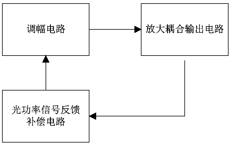
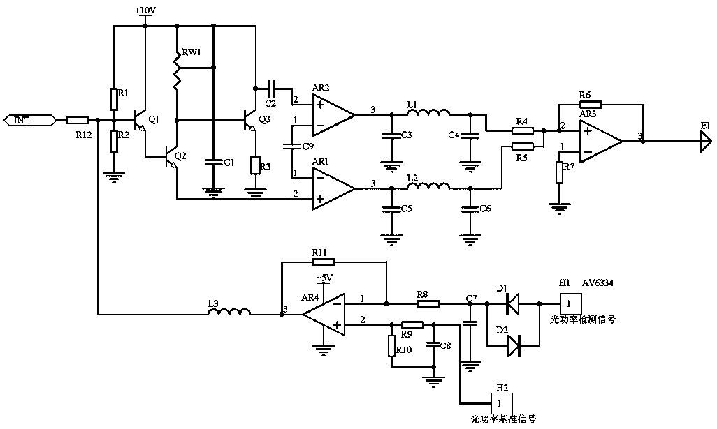
[0013] Embodiment 1, the optical network signal enhancement transmission circuit includes an optical power signal feedback compensation circuit, an amplitude modulation circuit, and an amplification coupling output circuit. The optical power signal feedback compensation circuit detects the optical power signal of the optical transmitter E1 and compares it with the optical power reference After the signal is relatively amplified, it is input into the amplitude modulation circuit, and the amplitude modulation circuit receives the electric power signal (for the power signal after electric modulation, how the electric signal is modulated, this is the prior art, and will not be described in detail here) and the optical power signal feedback compensation circuit The input signal is coupled, and then the amplitude is modulated by the compound circuit composed of transistors Q1, Q2, adjustable resistor RW1 and transistor Q3, and finally the amplification coupling output circuit is ampli...

Embodiment 2

[0016] Embodiment 2, on the basis of Embodiment 1, the optical power signal feedback compensation circuit uses an optical power meter to detect the size of the optical power signal emitted by the transmitter, and after limiting and filtering, enters the inverting input terminal of the operational amplifier AR4, Perform subtraction proportional operation with the optical power reference signal at the non-inverting input terminal (the signal size when the optical power signal emitted by the transmitter is normal), and output the amplified difference voltage, which is smoothed and filtered by the inductor L3 and coupled to the base of the transistor Q1 as a compensation signal Pole, including optical power detection signal port H1, optical power reference signal port H2, the size of the optical power signal emitted by the transmitter detected by the AV6334 optical power meter is connected to the anti-parallel diode D1 and diode through the optical power detection signal port H1 Th...


PUM


Abstract

The invention discloses an optical network signal enhancement emission circuit. An optical power signal feedback compensation circuit detects an optical power signal of an optical emitter E1, and inputs the optical power signal into an amplitude modulation circuit after comparing the optical power signal with an optical power reference signal and amplifying the optical power signal; the amplitudemodulation circuit receives an electric power signal and the signal input by the optical power signal feedback compensation circuit, couples the electric power signal with the signal, and then carriesout amplitude modulation by utilizing a composite circuit consisting of triodes Q1 and Q2, an adjustable resistor RW and a triode Q3; and finally, an amplification coupling output circuit applies anoperational amplifier AR1 to amplify, and simultaneously, a signal amplified and output by the operational amplifier AR1 and a reference potential output by an operational amplifier AR2 are input intoan adder AR3 together to be coupled and output. Stability of the optical power signal emitted by the emitter E1 is ensured; the problem of signal weakening in the long-distance transmission process of an optical network signal is solved; by regulating break-over voltages of the triodes Q1, Q2 and Q3, a resistance value of the adjustable resistor RW1 can be regulated, so that different types of optical power signals can be regulated; and the optical network signal enhancement emission circuit has very high development value and practical value.

Description

technical field [0001] The invention relates to the technical field of optical network signals, in particular to an optical network signal enhanced transmitting circuit. Background technique [0002] The active optical network is a point-to-multipoint optical communication system, which is composed of ONU, optical remote terminal OLT and optical fiber transmission lines. During the long-distance transmission of optical network signals, the signal often weakens. The main reason is that the signal transmitted by the optical network signal transmission circuit is unstable, contains clutter, and even contains abnormal signals, which leads to signal weakening during long-distance transmission. [0003] So the present invention provides a new solution to solve this problem. Contents of the invention [0004] In view of the above situation, in order to overcome the defects of the prior art, the purpose of the present invention is to provide an optical network signal enhancemen...

Claims


Application Information

Patent Timeline
IPC IPC(8): H04B10/50H04B10/54H04B10/564
CPCH04B10/50H04B10/541H04B10/564
Inventor 董刚松郝洋邵奇王正宋腾赵景隆赵豫京
Owner STATE GRID HENAN INFORMATION & TELECOMM CO
Why Eureka
Try Eureka