Fundus imaging equipment for clinical diagnosis

An imaging equipment and clinical diagnosis technology, which is applied to eye testing equipment, diagnosis, ophthalmoscope, etc., can solve the problems of inability to obtain video fundus images, insufficient image resolution, unsuitable for portability, etc., to reduce power requirements, fundus images Clear, compact system design

Inactive Publication Date: 2013-01-23
SUZHOU MICROCLEAR MEDICAL INSTR
View PDF16 Cites 20 Cited by
  • Summary
  • Abstract
  • Description
  • Claims
  • Application Information

AI Technical Summary

Problems solved by technology

[0008] 1) To overcome the problem that traditional fundus cameras can only take a single shot and cannot obtain video fundus images, the device of the present invention will output live images of the retina of the human eye through real-time video;
[0009] 2) To overcome the problem that the resolution of the single-exposure image of the traditional fundus camera is seriously insufficient, the device of the present invention will eliminate the stray light reflected back to the signal by the retina through confocal scanning technology, and obtain a high-resolution fundus image;
[0010] 3) To overcome the problem that the traditional fundus camera equipment is too large and not suitable for portability, the equipment of the present invention makes the system design more compact through technologies such as optical fiber input illumination beam and optical fiber output signal beam, and can be used for clinical diagnosis;

Method used


Image

  • Fundus imaging equipment for clinical diagnosis
  • Fundus imaging equipment for clinical diagnosis
  • Fundus imaging equipment for clinical diagnosis

Examples


Embodiment Construction

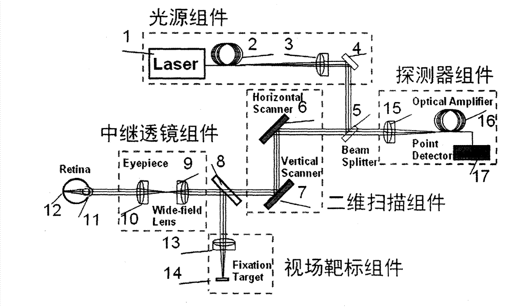
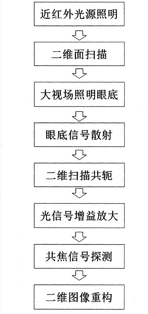
[0026] According to the manual attached figure 1 How to implement the function of a fundus imaging device for clinical diagnosis proposed by the present invention is described in detail as follows:

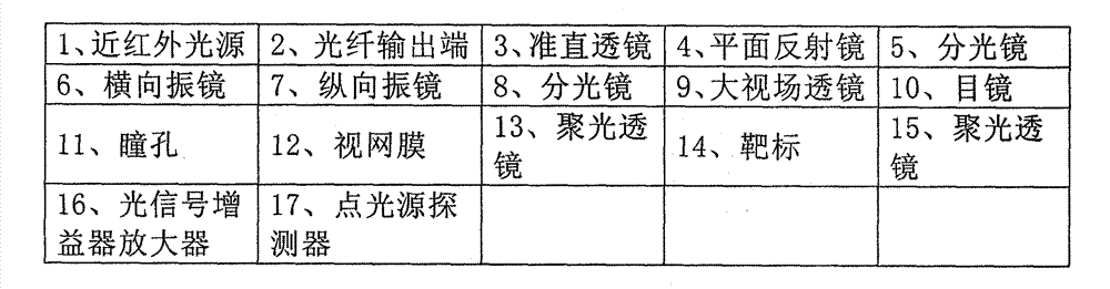
[0027] 1. The near-infrared light source (1) of the light source module outputs the illumination beam through the optical fiber port (2), becomes parallel light after passing through the collimating lens (3), and enters the beam splitter (5) after passing through the plane reflector (4); The beam splitter (5) reflects the illumination beam to the two-dimensional scanning assembly (6-7), and the typical splitting ratio of the beam splitter is 2:8, that is, 20% of the light beam energy is reflected into the two-dimensional scanning assembly; the beam splitter (5 The reason why the splitting ratio of ) is set to 80% transmission is to ensure that most of the signal beam reflected from the fundus of the human eye can enter the detector assembly.

[0028] 2. The illuminating beam ente...


PUM


Abstract

The invention discloses fundus imaging equipment for clinical diagnosis. The fundus imaging equipment for the clinical diagnosis consists of a light source component, a two-dimensional scanning component, a relay lens component, a detector component and a field-of-view target component. According to the fundus imaging equipment for the clinical diagnosis, an observation direction of a patient is fixed by utilizing the field-of-view target component, a retina of a human eye is scanned by using the two-dimensional scanning component, the detector component and an optical amplifier of the detector component optically enlarge a signal reflected by the retina to enhance the signal-to-noise ratio of an image, and a high-resolution image of the retina is acquired through the detection of a confocal signal; according to the fundus imaging equipment for the clinical diagnosis, the influence of field curvature and aberration in an imaging view field is reduced by the special design of a wide-field lens of the relay lens component, and the wide-field imaging of 30 to 60 degrees is realized by adjusting an eyepiece; high-resolution fundus imaging equipment which is compact is design and is applicable to the clinical diagnosis is fulfilled by the schemes of light source fiber input and optical signal fiber output, so that the imaging quality of the traditional fundus photography system is greatly improved, the imaging view field is greatly increased, and the clinical operability of equipment is strengthened; and the fundus imaging equipment for the clinical diagnosis particularly can acquire high-resolution images of retinas of human eyes under the condition that the retinas reflect weak signal light, and is used for the clinical diagnosis of fundus diseases.

Description

technical field [0001] The invention relates to a fundus imaging device, in particular to a fundus imaging device for clinical diagnosis, which is compact in design and easy to use. The image information of the field of view provides a basis for the diagnosis of fundus diseases. Background technique [0002] Fundus imaging equipment has always been an important scientific and clinical instrument in the field of diagnosis and treatment of ophthalmic diseases, and is an important auxiliary equipment to assist ophthalmologists in the diagnosis and treatment of fundus diseases; in 1999, US patents US5892569, US5923399, US3944341, etc. proposed to obtain human retina by scanning imaging Related image information also proposes the basic principle and structure of wide-field fundus imaging; the invention patent No. US5825533 (1998) proposes to carry out horizontal and vertical synchronous scanning through two independent scanning galvanometers, to Realize confocal scanning imaging...

Claims


Application Information

Patent Timeline
Patent Type & Authority Applications(China)
IPC IPC(8): A61B3/14A61B3/12
Inventor 李超宏
Owner SUZHOU MICROCLEAR MEDICAL INSTR
Why Eureka
Try Eureka