
Ultra-centrifugal dust remover adopting spraying device

A spray device and ultra-centrifugation technology, applied in the combination device, separation method, dispersed particle separation, etc., can solve the problems of large equipment and high requirements, and it is difficult for ordinary equipment to remove dust with extremely small particle size, etc., and achieve the spray angle range. Large, improve dust removal efficiency, improve the effect of sealing performance

Inactive Publication Date: 2018-05-22
宁波江北峰尚环保设备有限公司
View PDF2 Cites 3 Cited by
  • Summary
  • Abstract
  • Description
  • Claims
  • Application Information

AI Technical Summary

Problems solved by technology

[0003] However, most of the centrifugal dust collectors currently on the market are not equipped with spray devices, and only rely on the centrifugal force generated by the rotating air flow to separate the dust, while some dust with extremely small particle sizes need to increase the flow rate of the rotating air flow to remove them. Large requirements are high, and it is difficult for ordinary equipment to remove dust with extremely small particle sizes

Method used


Image

  • Ultra-centrifugal dust remover adopting spraying device
  • Ultra-centrifugal dust remover adopting spraying device
  • Ultra-centrifugal dust remover adopting spraying device

Examples


Embodiment Construction

[0017] The present invention will be described in further detail below by means of specific embodiments:

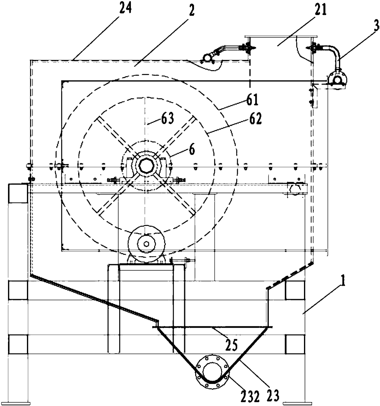
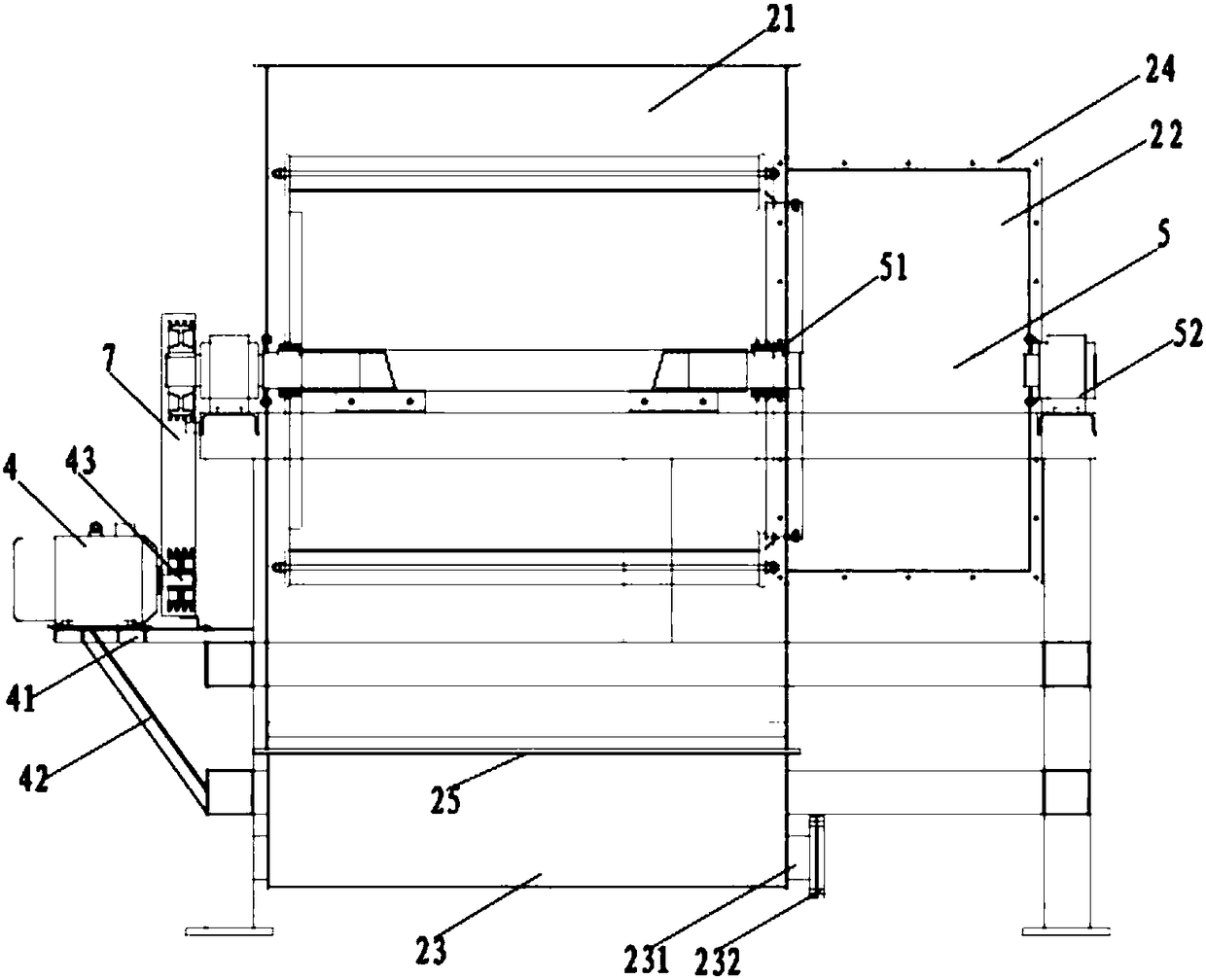
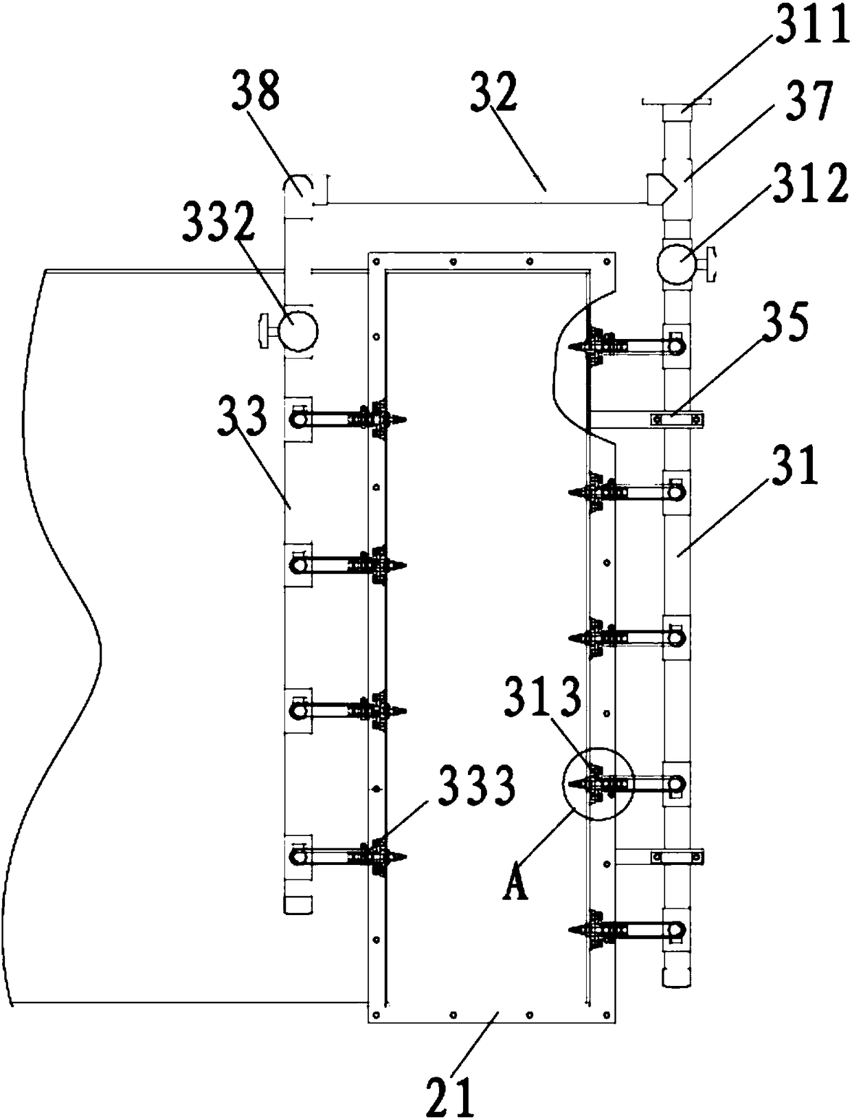
[0018] The reference signs in the accompanying drawings of the description include: frame 1, box body 2, air inlet 21, air outlet 22, sink 23, drain 231, end cover 232, protective cover 24, water seal tank 25, spray Device 3, the first water pipe 31, the main control valve 311, the first control valve 312, the first nozzle 313, the second water pipe 32, the third water pipe 33, the second control valve 332, the second nozzle 333, the connecting plate 35. Nozzle 36, two-way pipe joint 37, right-angle pipe joint 38, motor 4, motor mounting plate 41, inclined support plate 42, output shaft 43, rotating shaft 5, sealing ring 51, bearing seat 52, rotor 6, the first Filter screen 61 , second filter screen 62 , blade 63 , transmission device 7 .

[0019] refer to figure 1 and figure 2 , an ultracentrifugal dust collector using a spray device in the present invention, compris...


PUM


Abstract

The invention relates to the technical field of dust removing equipment and discloses an ultra-centrifugal dust remover adopting a spraying device. The ultra-centrifugal dust remover comprises a rack,a box body, a spraying device and a motor, wherein the box body and the motor are mounted on the rack; the box body comprises a gas inlet, a gas outlet and a downspout funnel; the gas inlet is formedin the top of the box body; the spraying device is mounted on the gas inlet; the gas outlet is formed in a side face of the box body; the downspout funnel is located below the box body; the box bodyis internally provided with a rotary shaft and a rotor; two ends of the rotary shaft are fixed at two sides of the rack respectively; the rotor sleeves the rotary shaft; the rotor is provided with a first filtering screen, a second filtering screen and a plurality of blades; the motor is connected with one end of the rotary shaft through a transmission device. According to the ultra-centrifugal dust remover disclosed by the invention, the spraying device is mounted at the gas inlet of the centrifugal dust removing equipment and water mist adsorbs dust so that a plurality of dust with small grain diameters becomes dust with relatively large grain diameters and the dust removing efficiency is improved; meanwhile, an inclined plane structure is arranged at the bottom of the box body so that water with the dust is convenient to collect by the downspout funnel.

Description

technical field [0001] The invention relates to the technical field of dust removal equipment, in particular to an ultracentrifugal dust collector. Background technique [0002] Centrifugal dust collector is one of the most widely used dust removal equipment in the industry. It is mostly used as equipment for smoke and dust removal, multi-stage dust removal and pre-dust removal for small coal-fired boilers. Its dust removal principle is similar to that of the reverse inertial force dust removal device. However, the dust-laden airflow in the inertial force dust collector is only affected by the shape of the equipment or the baffle, simply changing the direction of the streamline, and only makes half a circle or one circle; the airflow in the centrifugal force dust collector can rotate more than one circle, The swirling flow velocity is also greater, so the particles in the swirling air flow are subjected to a much stronger centrifugal force than gravity. For small-diameter,...

Claims


Application Information

Patent Timeline
Patent Type & Authority Applications(China)
IPC IPC(8): B01D50/00B01D45/14
CPCB01D45/14B01D50/10
Inventor 孙文清
Owner 宁波江北峰尚环保设备有限公司
Learn More