
Steel cylinder shot blasting machine

A shot blasting machine and steel cylinder technology, which is applied to abrasive jet machine tools, abrasives, metal processing equipment, etc., can solve the problems that shot blasting machines cannot handle efficiently, and achieve the effects of improving shot blasting efficiency, low cost and simple structure.

Pending Publication Date: 2018-05-22
盐城大丰荣盛除锈设备有限公司
View PDF6 Cites 0 Cited by
  • Summary
  • Abstract
  • Description
  • Claims
  • Application Information

AI Technical Summary

Problems solved by technology

[0003] The technical problem to be solved by the present invention is that the shot blasting machine in the prior art cannot efficiently process steel cylinders that require rough shot blasting

Method used


Image

  • Steel cylinder shot blasting machine
  • Steel cylinder shot blasting machine
  • Steel cylinder shot blasting machine

Examples


Embodiment 1

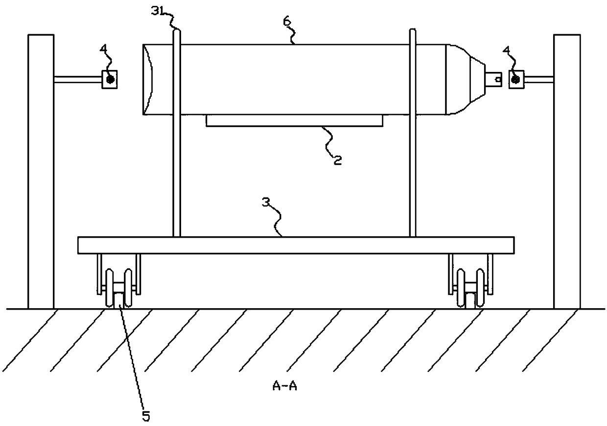
[0020] Such as figure 2 and image 3 As shown, the steel cylinder shot blasting machine of this embodiment includes a shot blasting chamber 1, a carrying platform 2, a traction trolley 3 and a protection steel rope 4;

[0021] The carrying platform 2 passes through the inside of the shot blasting chamber 1, such as Figure 4 and Figure 5 As shown, the carrying platform 2 is provided with a plurality of leak holes 21 with a square tapered cross section, and the leak holes 21 are used for the leakage of the pellets; a track 5 is installed below the carrying platform 2, and the track 5 is parallel to the carrying platform 2, and the traction trolley 3 The roller falls on track 5;

[0022] Three stations are arranged on the traction trolley 3, and each station includes four limit rods 31; Locate a steel cylinder 6; when the traction trolley 3 moves, the limit rod 31 drives the steel cylinder 6 to roll along the carrying platform 2;

[0023] Both sides of the bearing platfor...


PUM


Abstract

The invention discloses a steel cylinder shot blasting machine, which comprises a shot blasting chamber, a bearing platform and a traction trolley; the bearing platform passes through the inside of the shot blasting chamber; the traction trolley is positioned under the bearing platform; the moving track of the traction trolley is parallel to the bearing platform; one or more stations are arrangedon the traction trolley; each station comprises a plurality of position limiting rods; when a steel cylinder is transversely placed on the bearing platform, the position limiting rods are arranged attwo sides of the steel cylinder; each station locates one steel cylinder; when the traction trolley moves, the position limiting rods drive the steel cylinder to roll along the bearing platform. The steel cylinder shot blasting machine has the advantages that the traction trolley is used for driving the steel cylinder to roll on the bearing platform; a plurality of steel cylinders can be driven byone traction trolley once so as to pass through the shot blasting chamber at a higher speed; the steel cylinder shot blasting machine is very suitable for mass treatment of some steel cylinders requiring coarse shot blasting; the structure of the whole shot blasting machine is simple; the cost is low; the shot blasting efficiency is high.

Description

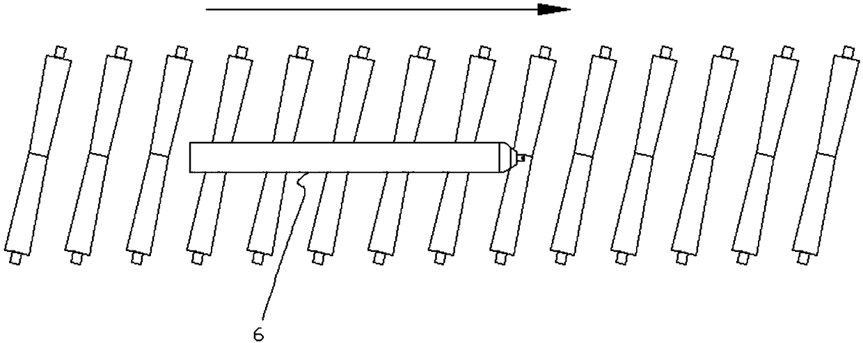
technical field [0001] The invention relates to the field of surface treatment equipment for mechanical parts, in particular to a steel cylinder shot blasting machine. Background technique [0002] Such as figure 1 As shown, in the prior art, a roller table shot blasting machine is used for shot blasting steel cylinders. All the rollers are arranged obliquely at the same angle. In fact, this special arrangement of rollers can make the steel cylinders advance along the roller table while rotating, so that each surface of the steel cylinders can be evenly treated by shot blasting. The disadvantage of the roller-type steel cylinder shot blasting machine is that the speed is slow. Even if the rotation speed of the roller is increased, it is difficult to increase the forward speed of the steel cylinder. It has the advantages, but it cannot adapt to some steel cylinders that require rough shot blasting. Contents of the invention [0003] The technical problem to be solved by ...

Claims


Application Information

Patent Timeline
Patent Type & Authority Applications(China)
IPC IPC(8): B24C1/10B24C3/08B24C3/10
CPCB24C1/10B24C3/083B24C3/10
Inventor 卢国荣
Owner 盐城大丰荣盛除锈设备有限公司
Learn More