
Automatic transmission device

A conveying device and automatic technology, applied in conveyors, loading/unloading, transportation and packaging, etc., can solve the problems of inability to effectively prevent items from slipping, no compaction structure, single use function, etc., to achieve convenient handling, Simple and novel structure, multi-functional effect

Inactive Publication Date: 2018-05-22
中山市榄商置业发展有限公司
View PDF4 Cites 0 Cited by
  • Summary
  • Abstract
  • Description
  • Claims
  • Application Information

AI Technical Summary

Problems solved by technology

[0003] The invention provides an automatic conveying device to solve the problems that the currently commonly used automatic conveying device is inconvenient to carry, does not have a compacting structure, has a single function, and cannot effectively prevent objects from slipping during the conveying process.

Method used

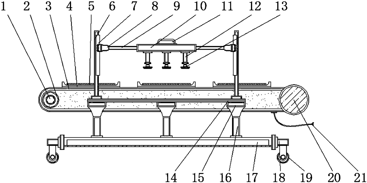

Image

  • Automatic transmission device
  • Automatic transmission device
  • Automatic transmission device

Examples


Embodiment Construction

[0015] The following will clearly and completely describe the technical solutions in the embodiments of the present invention with reference to the accompanying drawings in the embodiments of the present invention. Obviously, the described embodiments are only some, not all, embodiments of the present invention. Based on the embodiments of the present invention, all other embodiments obtained by persons of ordinary skill in the art without making creative efforts belong to the protection scope of the present invention.

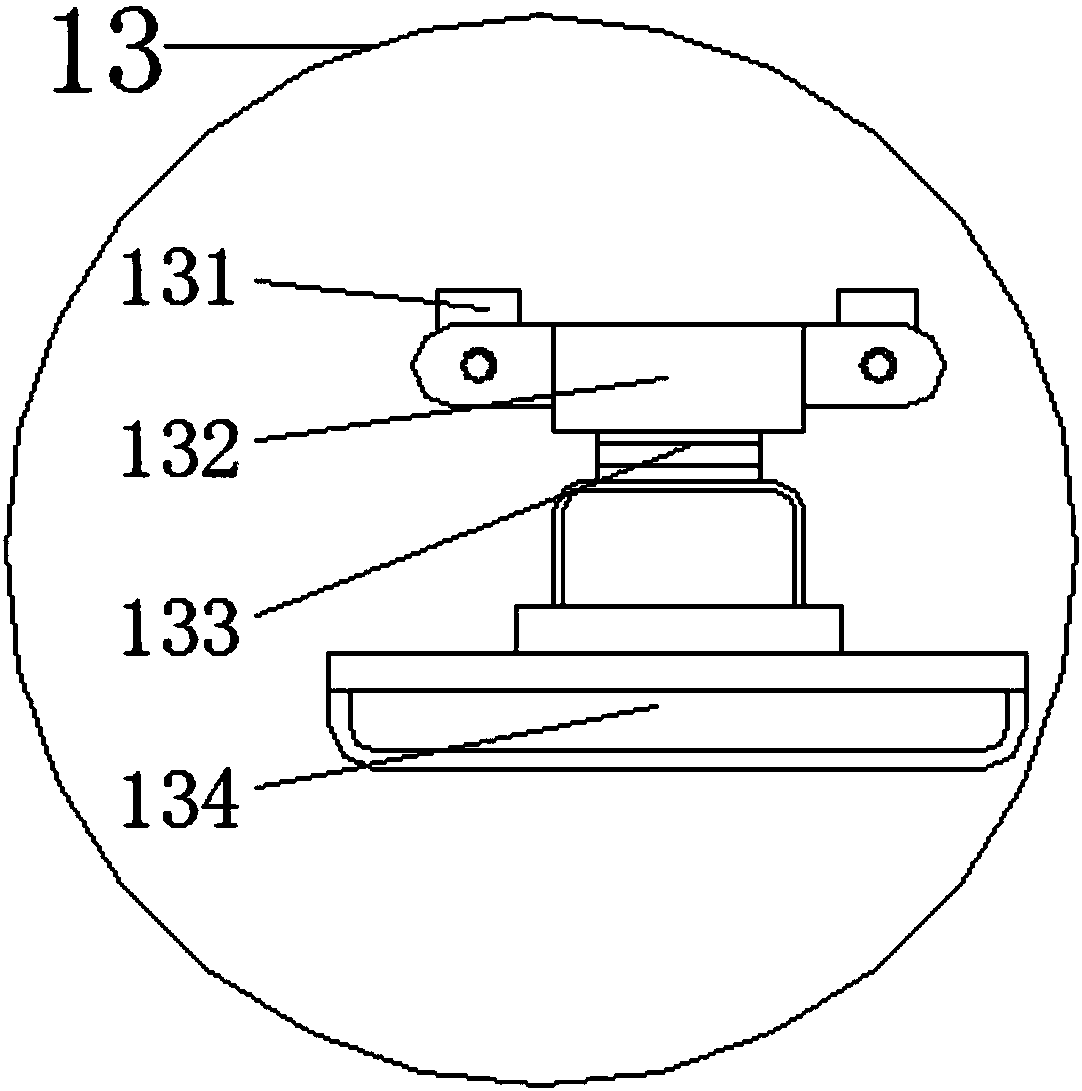
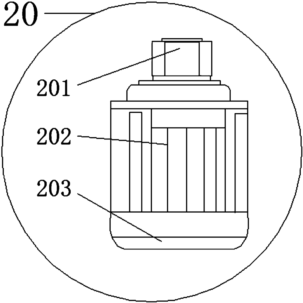
[0016] see Figure 1-3 , the present invention provides a technical solution: an automatic transmission device, including a rotating shaft 1, a bracket 6, a connecting rod 12, an engaging plate 14 and a motor 20, a rotating wheel 2 is installed on the outer side of the rotating shaft 1, and the rotating shaft 1 Through the connection between the runner 2 and the conveyor belt 3, the rotating shaft 1 is provided with a hexagonal groove, and the inner diameter o...


PUM


Abstract

The invention discloses an automatic transmission device comprising a rotating shaft, a support, a connecting rod, a link-connecting plate and an electric machine. The outer side of the rotating shaftis provided with a runner, and the rotating shaft is connected with a conveyor belt through the runner. The upper side of the conveyor belt is provided with a storage plate. The right side of a movable block is provided with a transverse frame, and two end openings of the connecting rod are fixedly connected with a fixed frame and a compacting device. The lower side of the connecting plate is provided with a fixed block, and the link-connecting plate is connected with a supporting rod through the fixed block. The bottom end of the support rod is provided with a base, and positioning plates are installed at the two end openings of the base. The lower sides of the positioning plates are provided with wheels, and the lower side of the electric machine is fixedly provided with an externally-connected power supply connecting wire. The automatic transmission device is simple and novel in structure and easy to operate, by setting a compacting device to compact the conveyed articles, the useof the transmission device has more functions, and the structure is relatively simple and the production cost is lower, and the automatic transmission device is suitable for large-scale production anduse.

Description

technical field [0001] The invention relates to the technical field of conveying equipment, in particular to an automatic conveying device. Background technique [0002] With the development of science and technology, the use of machinery is getting higher and higher. People continue to use mechanized equipment in the production process. In the shoemaking industry, the sole pressing process is one of the important processes. Due to the limitation of the production level of the industry, most shoe factories use semi-automatic sole pressing machines in the sole pressing process. The operation process of the existing sole press machines is to transport the shoes with the soles pasted by manual or automatic sole laminating machines on ordinary conveyor belts. Go to the sole pressing machine, place the shoes on the sole pressing machine manually, turn on the switch, the sole pressing machine will press the soles tightly, and then manually put the pressed shoes on the next conveyo...

Claims


Application Information

Patent Timeline
Patent Type & Authority Applications(China)
IPC IPC(8): B65G15/30B65G69/20
Inventor 梁荣强
Owner 中山市榄商置业发展有限公司
Learn More