Cantilevered large-flying-wing unit type curtain wall system and installing method thereof

A unitary, flying-wing technology, applied in the field of exterior decorative curtain walls, can solve the problems of large impact on construction quality, complex procedures, slow construction progress, etc., and achieve the effect of reducing construction and installation procedures, ensuring appearance effects, and reducing overall costs.

Inactive Publication Date: 2018-05-22
JANGHO GRP
View PDF5 Cites 4 Cited by
  • Summary
  • Abstract
  • Description
  • Claims
  • Application Information

AI Technical Summary

Problems solved by technology

[0003] 1. The scattered parts of the large flying wing, such as the installation of the support, the keel and the panel, and the sealing and gluing, are all installed on-site. The on-site construction process is complicated, and it is greatly affected by the construction quality, so it is difficult to guarantee the appearance of the building;
[0004] 2. The steel keel welding connection method used in the past for the cantilevered large flying wing requires many on-site welding procedures, and there are potential fire safety hazards;
[0005] 3. Ordinary frame structure system, the construction progress is slow, and the construction accuracy is difficult to control

Method used


Image

  • Cantilevered large-flying-wing unit type curtain wall system and installing method thereof
  • Cantilevered large-flying-wing unit type curtain wall system and installing method thereof
  • Cantilevered large-flying-wing unit type curtain wall system and installing method thereof

Examples


Embodiment Construction

[0031] In order to fully illustrate the technical means and creative features for realizing the present invention, the present invention will be further described below in conjunction with specific embodiments.

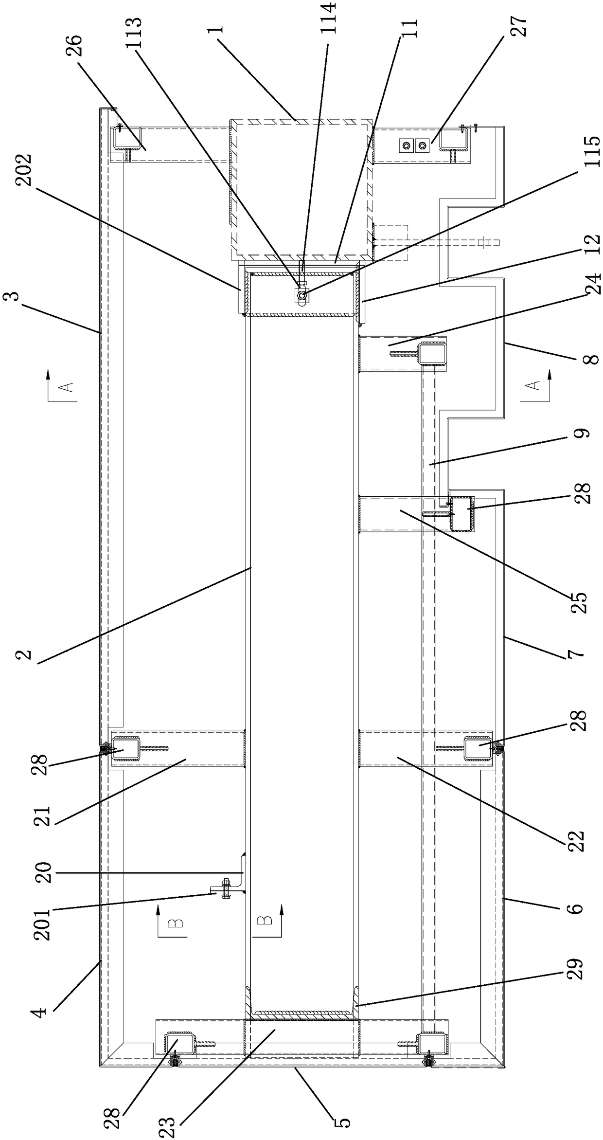
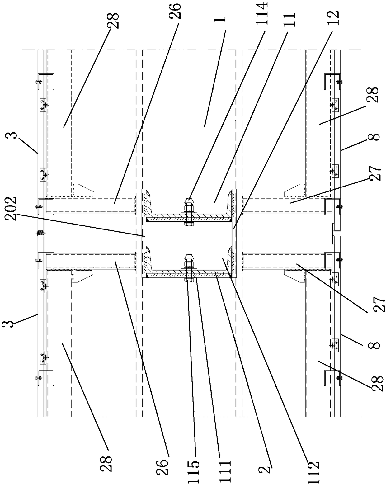
[0032] Such as Figure 1-Figure 3 As shown, the present invention provides a cantilevered large flying wing unit type curtain wall system, which includes a horizontal main body steel beam 1 fixed to the building main body and several flying wing units. The outer surface of the main body steel beam 1 is fixedly provided with several L-shaped connecting angle brackets 11 . The connecting angle bracket 11 has a first surface 111 and a second surface 112 perpendicular to each other, the first surface 111 is fixedly connected with the main body steel beam 1 , and the second surface 112 is provided with a horizontal adjusting slot 113 . The first surface 111 is fixedly connected to the main body beam 1 by connecting bolts 114 , and at the same time is fixedly connected by ...


PUM


Abstract

Disclosed are a cantilevered large-flying-wing unit type curtain wall system and an installing method thereof. The curtain wall system comprises a main body steel beam and flying wing units. The outerside surface of the main body steel beam is provided with a plurality of connecting corner connectors. Each flying wing unit comprises two flying wing crossbeams. The inner end of each flying wing crossbeam is fixed to the inner side of the corresponding connecting corner connector. The flying wing crossbeams are fixedly connected with a first connecting beam, a second connecting beam, a third connecting beam, a fourth connecting beam and a fifth connecting beam. The top surface and the bottom surface of the main body steel beam are fixedly connected with a sixth connecting beam and a seventhconnecting beam correspondingly. In the same flying wing unit, the tail ends of the corresponding first connecting beam, the second connecting beam, the third connecting beam, the fourth connecting beam, the fifth connecting beam, the sixth connecting beam and the seventh connecting beam are connected through a supporting crossbeam. The exterior of each flying wing unit is provided with a first aluminum plate, a second aluminum plate, a third aluminum plate, a fourth aluminum plate, a fifth aluminum plate and a sixth aluminum plate. According to the cantilevered large-flying-wing unit type curtain wall system and the installing method thereof, the on-site installation procedure can be reduced, the installation cost is reduced greatly, and the appearance effect of a building can be effectively ensured.

Description

technical field [0001] The invention belongs to the technical field of exterior decorative curtain walls, in particular to a cantilevered large flying wing unitized curtain wall system and an installation method thereof. Background technique [0002] In the existing cantilevered large flying wing unitized curtain wall, the cantilevered large flying wing part usually adopts a frame structure system, the keel is made of aluminum alloy profiles or steel parts, and the scattered components are processed in a factory, and are transported to the site after processing Install. This kind of mode has the following disadvantages: [0003] 1. The scattered parts of the large flying wing, such as the installation of the support, the keel and the panel, and the sealing and gluing, are all installed on-site. The on-site construction process is complicated, and it is greatly affected by the construction quality, so it is difficult to guarantee the appearance of the building; [0004] 2. ...

Claims


Application Information

Patent Timeline
Patent Type & Authority Applications(China)
IPC IPC(8): E04B2/88E04B2/96
CPCE04B2/88E04B2/96E04B2/965
Inventor 付小兵龚导彭群兰亦标李锋
Owner JANGHO GRP
Why Eureka
Try Eureka