Concrete construction vibrating device and construction method

A technology of vibrating device and construction method, which is applied in construction, building structure, processing of building materials, etc., can solve the problems of large error in results and inability to intuitively reflect the compactness of artificially vibrated concrete, so as to reduce over-vibration. and under-vibration, reducing over-vibration and leakage, avoiding the effects of under-vibration and over-vibration

Inactive Publication Date: 2018-05-22
SHANGHAI CONSTRUCTION GROUP
View PDF8 Cites 7 Cited by
  • Summary
  • Abstract
  • Description
  • Claims
  • Application Information

AI Technical Summary

Problems solved by technology

However, the phenomenon of leakage and over-vibration caused by manual operation is unavoidable. The monitored vibration time can only be used as an indirect indicator of the compactness of vibration. Spend

Method used


Image

  • Concrete construction vibrating device and construction method
  • Concrete construction vibrating device and construction method
  • Concrete construction vibrating device and construction method

Examples


Embodiment Construction

[0045] The present invention will be further described in detail below in conjunction with the accompanying drawings and specific embodiments. According to the description below, the purpose, technical solution and advantages of the present invention will be more clear. It should be noted that the described embodiments are preferred embodiments of the present invention, but not all embodiments.

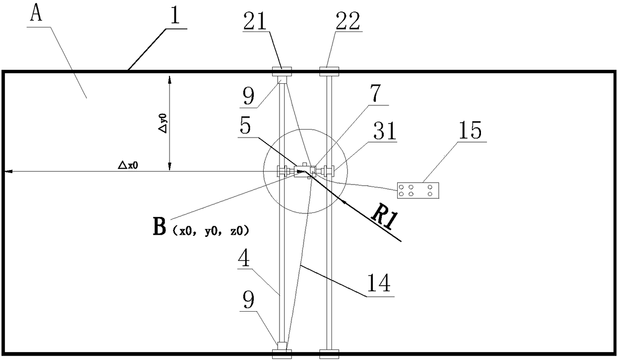
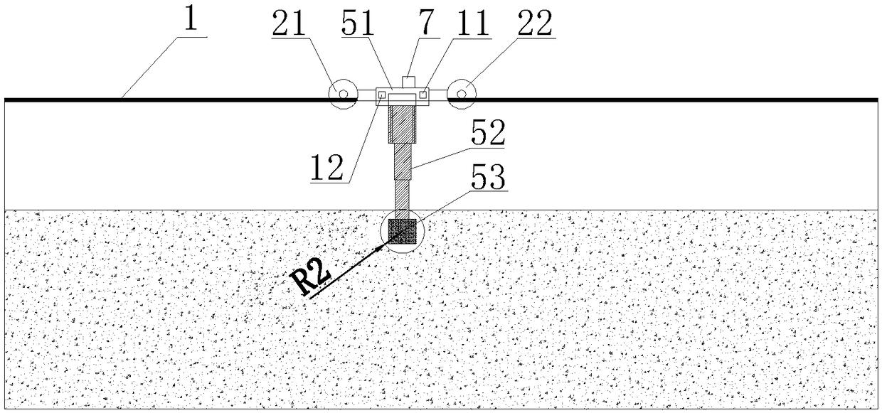
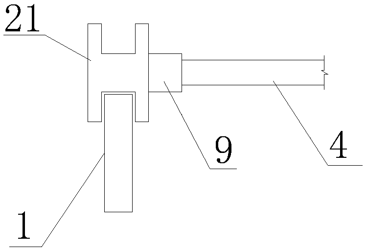
[0046] combine figure 1 , figure 2 shown and refer to Figure 7 , a vibrating device for concrete construction, comprising two transverse guide rails 1, longitudinal guide rails 4 appearing in pairs, a telescopic vibrating rod 5, a brake system 7 installed on the top of the telescopic vibrating rod 5, and a data acquisition card 8 and monitoring computer 10. Among them, two transverse guide rails are installed at the boundary position of construction area A. One of the longitudinal guide rails 4 is equipped with a driving wheel 21 controlled by a drive motor 9 at both ends, and ...


PUM


Abstract

The invention relates to a concrete construction vibrating device, and further relates to a construction method of the vibrating device. The concrete construction vibrating device comprises two transverse guiding rails, longitudinal guiding rails appearing in pairs, a telescopic-type vibrating bar, a braking system, a data acquisition card and a monitoring computer. Drive wheels are mounted at thetwo ends of one of the longitudinal guiding rails. Driven wheels are mounted at the two ends of the other longitudinal guiding rail. The drive wheels and the driven wheels are mounted on the transverse guiding rails. Driving wheels are mounted on the longitudinal guiding rails correspondingly. A connecting rod is connected to the position between the driving wheels of the two longitudinal guidingrails. A vibrating induction timer and a laser displacement sensor are mounted on the telescopic-type vibrating bar. The braking system is connected with each driving motor and a control handle. Thedata acquisition card is connected with the vibrating induction timer and the laser displacement sensor through signal lines. According to the concrete construction vibrating device, 4D (x, y, z, t) real-time monitoring of stereo gridding of the concrete vibrating quality can be achieved, and the situations of over vibration and being lack of vibration are reduced.

Description

technical field [0001] The invention relates to a vibrating device and a construction method for concrete construction, in particular to a vibrating device and a construction method for three-dimensional grid construction of concrete, belonging to the technical field of construction and municipal engineering construction. Background technique [0002] Vibration of concrete refers to vibrating in layers in an orderly manner according to the length of the vibrating rod and the effective radius of the vibration. The moving distance of the vibrating rod can generally be about 40cm, and the depth of the vibrating rod inserted into the vibrated concrete of the lower layer should not be less than 5cm , The vibration time of each point should be 20-30s, the concrete will no longer sink, no air bubbles will appear, and the surface will be flooded to prevent leakage or over-vibration. Traditional large-volume concrete vibration requires manual labor to maintain a certain vibration dep...

Claims


Application Information

Patent Timeline
Patent Type & Authority Applications(China)
IPC IPC(8): E04G21/08
Inventor 王新新吴小建张阿晋
Owner SHANGHAI CONSTRUCTION GROUP
Why Eureka
Try Eureka