A multi-unit composite spiral plate heat exchanger

A spiral plate type, heat exchanger technology, applied in indirect heat exchangers, heat exchanger types, laminated components, etc., can solve the problem of difficult real-time monitoring of the effectiveness of internal structures, difficult to obtain local blockages in real time, and difficult heat exchange plate depth. Cleaning and other problems, to achieve the effect of easy modular expansion, easy modular processing and assembly, and high heat transfer efficiency

Active Publication Date: 2019-09-10
INST OF PROCESS ENG CHINESE ACAD OF SCI
View PDF5 Cites 3 Cited by
  • Summary
  • Abstract
  • Description
  • Claims
  • Application Information

AI Technical Summary

Problems solved by technology

[0004] To sum up, in recent years, there have been a variety of treatment methods to improve the heat transfer efficiency of the spiral plate heat exchanger and reduce the processing difficulty by adjusting the surface structure of the spiral plate and changing the channel size. Due to the characteristics of wide flow channels, there are still the following shortcomings that need to be overcome: 1. The distribution of the flow field is uneven, especially when the local flow channels are blocked, dead zones are prone to appear, which affects the heat exchange efficiency; 2. It is difficult to effectively control the internal structure. For example, it is difficult to obtain local blockage in real time; 3. Due to the existence of support structures such as fixed-distance columns, it is difficult to perform deep cleaning on the heat exchange plate; 4. Due to the low degree of modularization, if the spiral plate is partially corroded, Leakage, etc., high maintenance and replacement costs

Method used


Image

  • A multi-unit composite spiral plate heat exchanger
  • A multi-unit composite spiral plate heat exchanger
  • A multi-unit composite spiral plate heat exchanger

Examples


Embodiment 1

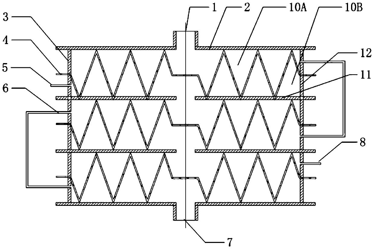
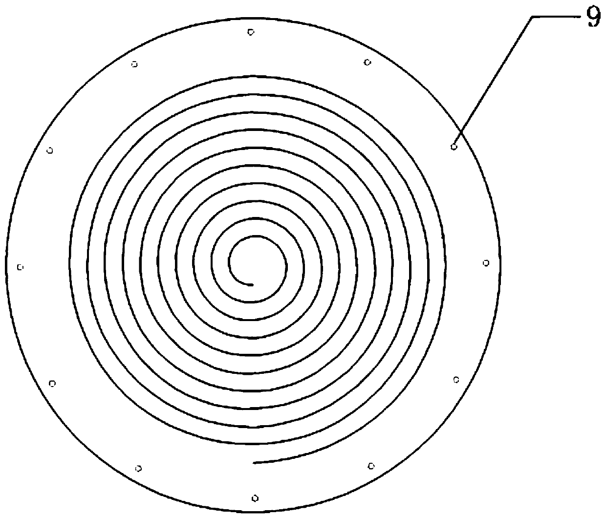
[0027] This embodiment discloses a multi-unit composite spiral plate heat exchanger. Such as figure 1 and figure 2 As shown, the multi-unit composite spiral plate heat exchanger includes a plurality of vertically stacked heat exchange units. The heat exchange unit includes a metal plate 4 with a spiral groove, an upper cover plate 2 with a central hole, and a central hole. The lower cover plate 11, and the first side plate 3 provided with the first fluid port and the second side plate 12 provided with the second fluid port. The heat exchange unit is divided into an upper flow channel 10A and a lower flow channel 10B by the metal plate 4, and the upper flow channel 10A and the lower flow channel 10B are both spiral. The edge of the metal plate 4 with the spiral groove is a planar structure, and is provided with a plurality of connection holes 9 . A plurality of connection holes are provided at the edges of the upper cover plate 2 and the lower cover plate 11 . The bottom s...

Embodiment 2

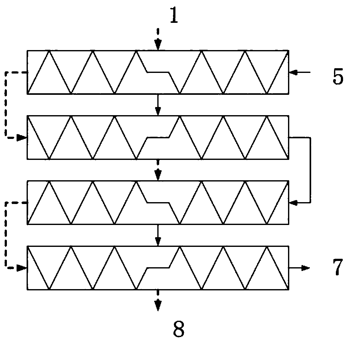
[0031] In this embodiment, the structure of the same multi-unit composite spiral plate heat exchanger as in Embodiment 1 will not be repeated, and the parallel flow heat exchange or countercurrent heat exchange in this embodiment will be described in detail below.

[0032] see Figure 4 , as shown by the dotted line in the figure, the flow direction of the hot-side fluid is consistent with that of Example 1. The hot-side fluid flows in from the hot-side fluid inlet 1 in the center of the first heat exchange unit, and flows through the first heat exchange unit from the inside to the outside. The spiral upper flow channel flows into the spiral lower flow channel of the second heat exchange unit through the side connecting pipe, and flows through the spiral lower flow channel from outside to inside, and then passes between the second heat exchange unit and the third heat exchange unit The central hole of the shared cover plate flows into the spiral upper flow channel of the third...


PUM


Abstract

The invention discloses a multi-unit composite spiral plate type heat exchanger and belongs to the technical field of heat exchange equipment. The heat exchanger is designed for overcoming the defectthat an existing spiral plate type heat exchanger cannot overcome the defects of flow way blockage and difficult deep cleaning. The multi-unit composite spiral plate type heat exchanger comprises multiple heat exchange units, wherein each heat exchange unit is provided with a metal plate with a spiral groove, an upper cover plate, a lower cover plate, a first side plate with a first fluid port anda second side plate with a second fluid port. The heat exchange units are divided by metal plates into upper flow ways and lower flow ways. The metal plates, the upper cover plate, the lower cover plate and the side plates are fixedly connected through fasteners. The heat exchange units are perpendicularly stacked and share the adjacent cover plate, the heat exchange units are arranged in a composite mode, fluid in the flow ways of the heat exchange units is arranged in the mode of cold-hot-hot-cold mode. The characteristics of a plate type heat exchanger and a spiral plate type heat exchanger are combined, the structure is compact, the heat exchange efficiency is high, modular extension is convenient, and the multi-unit composite spiral plate type heat exchanger has the advantages of being easy to machine and easy to detach and clean.

Description

technical field [0001] The invention relates to the technical field of heat exchange equipment, in particular to a multi-unit composite spiral plate heat exchanger. Background technique [0002] The heat exchanger is an energy-saving device for heat transfer between two or more fluids at different temperatures, and it is also one of the main devices for improving energy utilization. There are many kinds of heat exchangers. Among them, the spiral plate heat exchanger is made of two parallel metal plates coiled into two spiral channels. It has the characteristics of large heat exchange area, good heat transfer performance, and simple processing. It is widely used in electric power, petrochemical , medicine and other fields. [0003] In 1930, the Swedish ROSENBLAD company first proposed the spiral plate heat exchanger structure. The subsequent development mainly focused on reducing the difficulty of the manufacturing process and improving the heat exchange efficiency, and prop...

Claims


Application Information

Patent Timeline
Patent Type & Authority Patents(China)
IPC IPC(8): F28D9/04F28F3/04F28F27/00
CPCF28D9/04F28F3/04F28F27/00
Inventor 杨超徐俊波张伟鹏
Owner INST OF PROCESS ENG CHINESE ACAD OF SCI
Why Eureka
Try Eureka