
Radial flow equalization pressure swing adsorption tower

A pressure swing adsorption and adsorption chamber technology, applied in the separation of dispersed particles, chemical instruments and methods, separation methods, etc., can solve the problems of unreasonable airflow distribution, uneven flow field distribution, large flow resistance, etc., and achieve improved gas production. Efficiency and gas production quality, uniform flow field distribution, reasonable airflow distribution

Inactive Publication Date: 2019-09-06
NORTHEASTERN UNIV
View PDF9 Cites 2 Cited by
  • Summary
  • Abstract
  • Description
  • Claims
  • Application Information

AI Technical Summary

Problems solved by technology

For the axial flow adsorption tower, it takes a long time for the gas to flow through the adsorbent filling area, resulting in a large pressure drop, resulting in a large flow resistance, so easy to cause the adsorbent at the inlet and outlet ends to be broken, so it is not suitable for large load operating conditions
For the radial flow adsorption tower, the gas takes a shorter time to flow through the adsorbent filling area, has a higher circulation rate, and the gas production is also higher, but the traditional radial flow adsorption tower still has some defects
[0004] Taking pressure swing adsorption cycle oxygen production as an example, when a traditional (Z-type or Π-type) radial flow adsorption tower is used, the problem of uneven distribution of the flow field is very likely to occur during the adsorption stage and the backflushing stage. It will cause local flow dead zone, resulting in unreasonable air distribution during gas production and incomplete purging during backflushing, which will affect the gas production efficiency and gas quality

Method used


Image

  • Radial flow equalization pressure swing adsorption tower
  • Radial flow equalization pressure swing adsorption tower
  • Radial flow equalization pressure swing adsorption tower

Examples


Embodiment Construction

[0017] The present invention will be further described in detail below in conjunction with the accompanying drawings and specific embodiments.

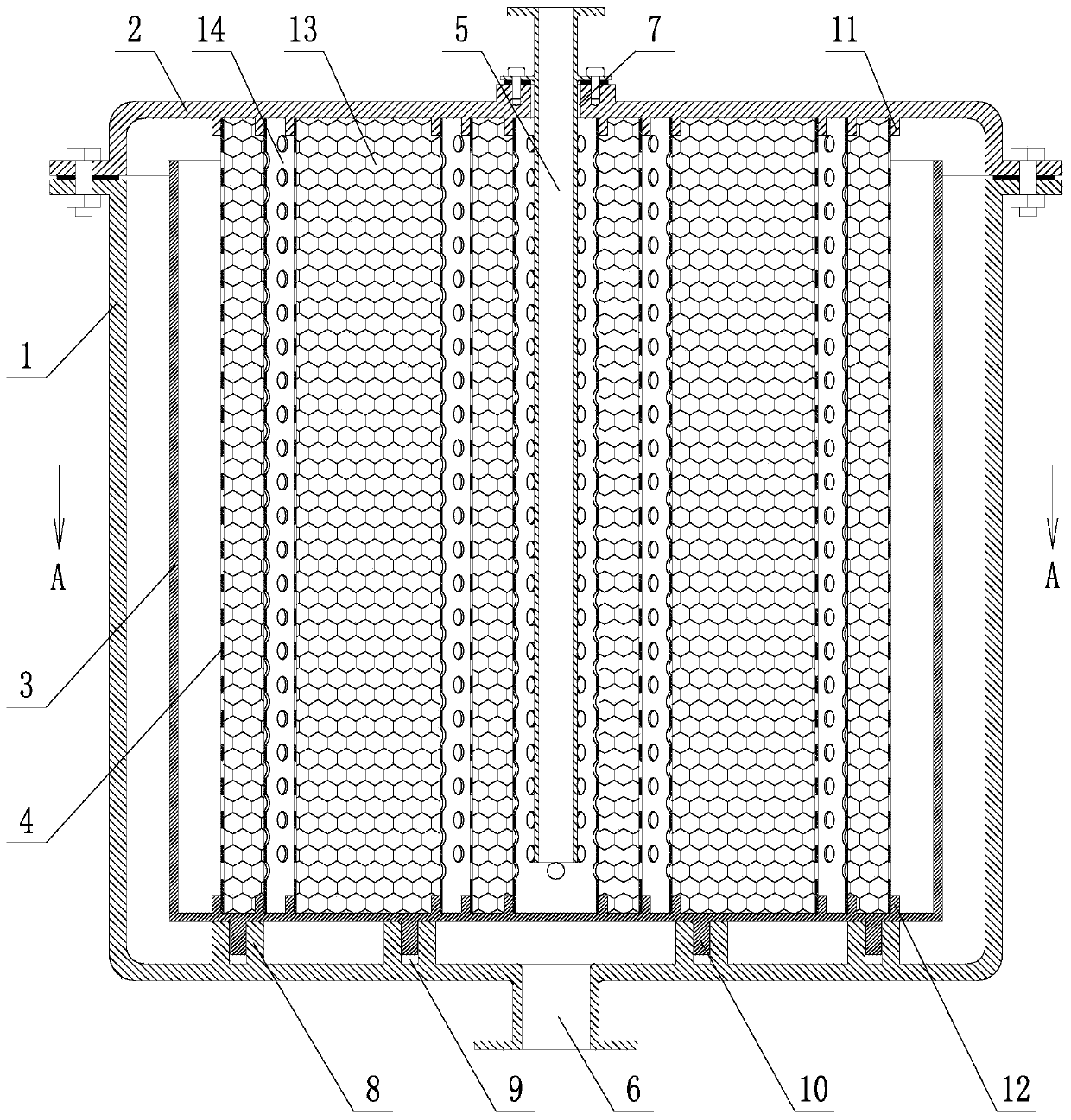
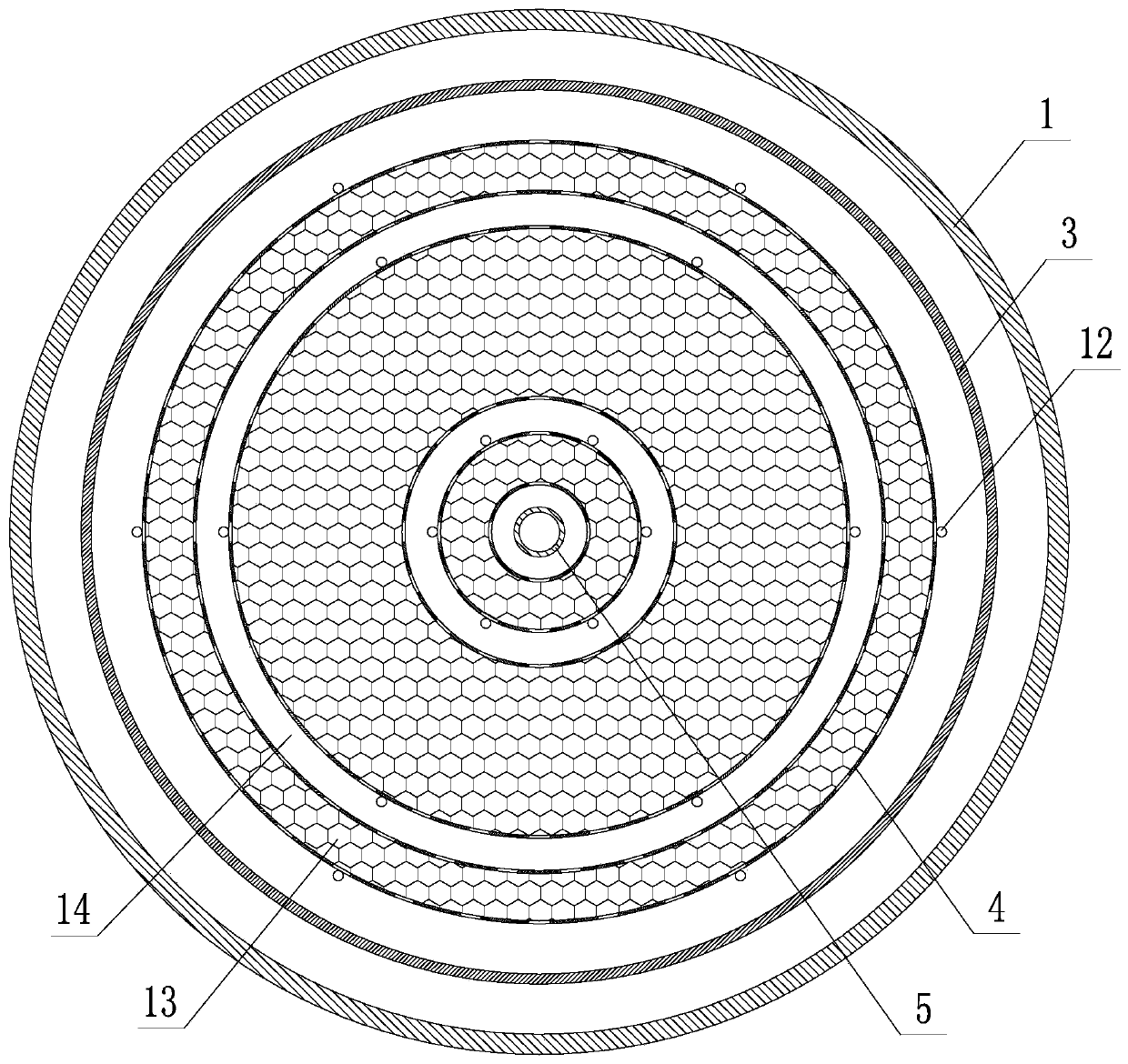
[0018] Such as figure 1 , 2 As shown, a radial flow equalization and pressure swing adsorption tower includes a shell 1, a cover 2, a guide tube 3, an air distribution tube 4 and a ventilation pipe 5; the shell 1 adopts a cylindrical structure, and the shell 1 is vertical The center of the bottom plate of the shell 1 is provided with a vent 6, the top of the shell 1 is an open structure, and the cover 2 is sealed and fixed on the top opening of the shell 1; hole 7, the vent pipe 5 is vertically inserted in the vent pipe jack 7, the pipe body of the vent pipe 5 is sealed and fixedly connected with the vent pipe jack 7, the lower end nozzle of the vent pipe 5 is located inside the shell 1, and the vent pipe 5. The nozzle at the upper end is located outside the cover 2; a number of support blocks 8 are provided on the upper surface of ...


PUM


Abstract

The invention relates to a radial flow equalization pressure swing adsorption tower, which comprises an outer shell, a sealing cover, a flow guiding cylinder, wind distribution cylinders and a ventingpipe, wherein a venting port is arranged on the bottom portion of the outer shell, the venting pipe is inserted in the center of the sealing cover, and extends into the outer shell, the flow guidingcylinder is concentrically arranged in the outer shell, support blocks are arranged in front of the bottom plates of the flow guiding cylinder and the outer shell, the support blocks and the flow guiding cylinder are positioned by positioning pins and positioning holes, the wind distribution cylinders are concentrically arranged inside the flow guiding cylinder, and are fixedly arranged between the sealing cover and the bottom plate of the flow guiding cylinder through positioning snapping blocks, the surface of the wind distribution cylinder is uniformly provided with gas-permeable holes, a plurality of the wind distribution cylinders are arranged and have different diameters, the plurality of the wind distribution cylinders are arranged concentrically, the circumferential gaps between the wind distribution cylinders are respectively arranged as adsorption chambers and gas chambers, the adsorption chambers and the gas chambers are alternately distributed in the radial direction, and the adsorption chamber is filled with an adsorbent. According to the present invention, at the adsorption phase and the backflush stage, the flow field inside the adsorption tower is uniformly distributed, the gas flow distribution is reasonable during the gas producing, and the purging is clean and complete during the backflushing, such that the gas production efficiency and the gas production quality can be effectively improved.

Description

technical field [0001] The invention belongs to the technical field of industrial gas separation, in particular to a radial equal flow pressure swing adsorption tower. Background technique [0002] The pressure swing adsorption process is mainly used for the production of oxygen enrichment, desulfurization, and CO removal 2 etc., because of its simple process, convenient operation, normal temperature operation, low equipment maintenance rate, low energy consumption, high degree of automation, and high purity of gas production, it has been widely used in the field of industrial gas separation. [0003] As the core equipment in the pressure swing adsorption process, the pressure swing adsorption tower can be divided into axial flow adsorption tower and radial flow adsorption tower. For the axial flow adsorption tower, it takes a long time for the gas to flow through the adsorbent filling area, resulting in a large pressure drop, resulting in a large flow resistance, so easy t...

Claims


Application Information

Patent Timeline
Patent Type & Authority Applications(China)
IPC IPC(8): B01D53/047
CPCB01D53/047
Inventor 冯明杰徐凤森周帅磊郭奕毛成
Owner NORTHEASTERN UNIV
Learn More