
Wafer surface drying and purging equipment

A technology for surface drying and purging equipment, used in electrical components, semiconductor/solid-state device manufacturing, circuits, etc., and can solve problems such as poor versatility

Pending Publication Date: 2021-03-16
芯米(厦门)半导体设备有限公司
View PDF1 Cites 0 Cited by
  • Summary
  • Abstract
  • Description
  • Claims
  • Application Information

AI Technical Summary

Problems solved by technology

However, the above solution can only clean the surface of a wafer of one specification, and has poor versatility; and after cleaning the surface of the wafer, the wafer needs to be moved to another drying device for drying

Method used


Image

  • Wafer surface drying and purging equipment
  • Wafer surface drying and purging equipment
  • Wafer surface drying and purging equipment

Examples


Embodiment Construction

[0028] Next, the technical solutions in the embodiments of the present invention will be apparent from the embodiment of the present invention, and it is clearly described, and it is understood that the described embodiments are merely embodiments of the present invention, not all of the embodiments. Based on the embodiments of the present invention, there are all other embodiments obtained without making creative labor without making creative labor premises.

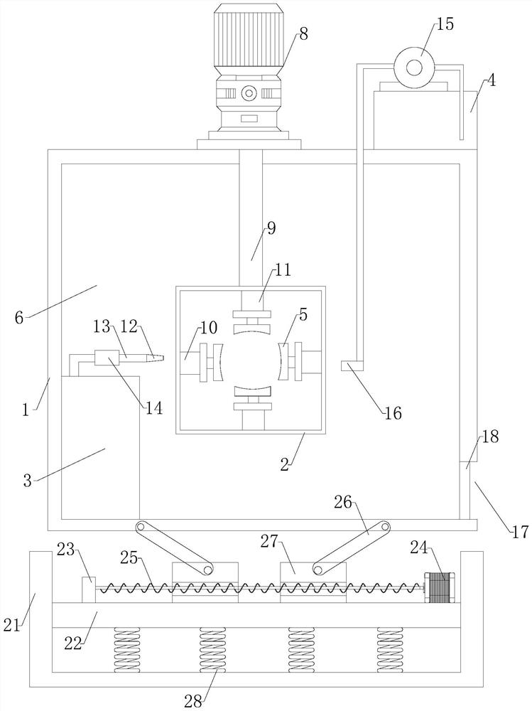
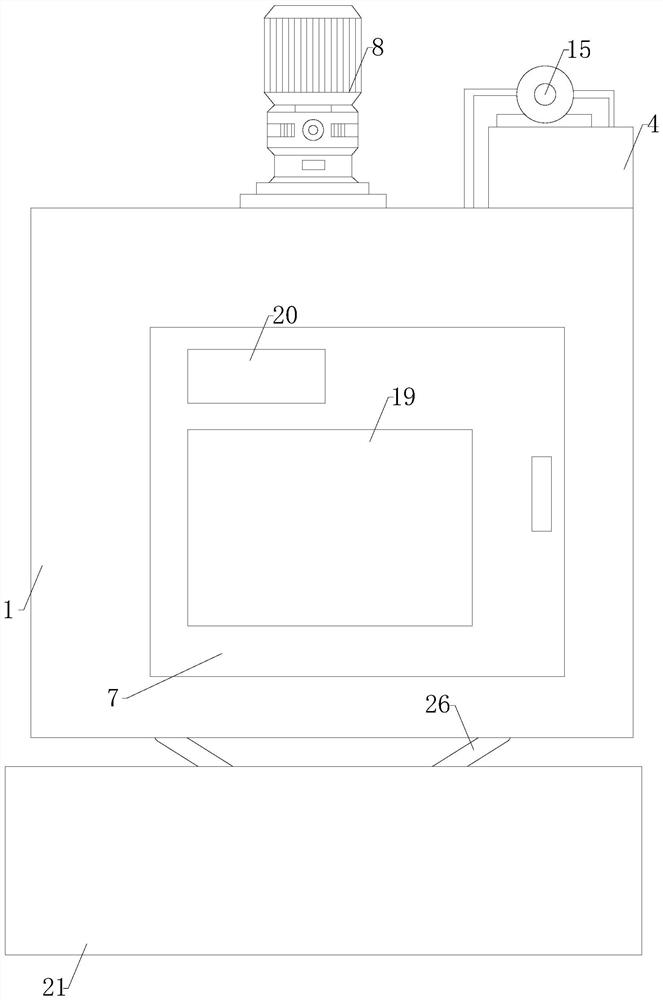
[0029] See Figure 1-3 The wafer surface is dry purge apparatus, including frame 1, drying frame 2, nitrogen supply device 3, cleaning tank 4, and clamping block 5.

[0030] The rack 1 has a built-in working cavity 6, and the working cavity 6 front end is set to seal the door 7 (eg figure 2 ). The working cavity 6 can be a stereo space chamber. The sealing door 7 can have a corresponding handle (unmarked), and the sealing door 7 is moderate.

[0031] The rack 1 is provided at the top end of the driver 8, and the drive motor...


PUM


Abstract

The invention provides wafer surface drying and purging equipment, which comprises a rack, a drying frame, a nitrogen supply device, a cleaning box and a clamping block, wherein a working cavity is formed in the rack, a sealing door is arranged at the front end of the working cavity, a driving motor is arranged at the top end of the rack, a rotating rod is arranged at the output end of the drivingmotor, the end, away from the driving motor, of the rotating rod penetrates through the side wall of the rack and stretches into the working cavity, a drying frame is arranged at the end, away from the driving motor, of the rotating rod, the drying frame is a rectangular frame, first hydraulic rods are arranged on the inner walls of the left side and the right side of the drying frame, second hydraulic rods are arranged on the upper side wall and the lower side wall of the drying frame, clamping blocks are arranged at the output ends of the first hydraulic rod and the second hydraulic rod, grooves are formed in the ends, away from the side wall of the drying frame, of the clamping blocks, a nitrogen supply device is arranged at the bottom end of the left side of the working cavity, a nitrogen nozzle is arranged on the working cavity and located on the left side of the drying frame, and a conveying pipeline is arranged between the output end of the nitrogen supply device and the nitrogen nozzle.

Description

Technical field [0001] The present invention relates to the field of wafer cleaning, and in particular, a wafer surface dry purge apparatus. Background technique [0002] The wafer is the most commonly used semiconductor material, and is also a carrier used in the smart chip, as a circle is circular, referred to as a wafer. After the wafer is completed, the wafer is attached to an approximately 2 μm Al. 2 O 3 And the glycerol mixed liquid protection layer (hereinafter referred to as the protective layer), the wafer first needs to be cleaned before making a smart chip. [0003] The wafer production surface cleaning apparatus is a auxiliary device for wafer, a protective layer that is dissolved on a protective layer thereof in the surface, is widely used in wafer production. The general wafer produces a surface cleaning device, and the multi-set wafer is placed directly on the mesh, causing a multi-set wafer to be placed, stacked with each other, and chemical solutions in the proce...

Claims


Application Information

Patent Timeline
Patent Type & Authority Applications(China)
IPC IPC(8): H01L21/67
CPCH01L21/67034H01L21/67028H01L21/67023
Inventor 许志雄
Owner 芯米(厦门)半导体设备有限公司
Learn More