Position detecting device, lens drive device, camera device, and electronic equipment

A lens driving device and detection device technology, which is applied in the direction of the camera's focusing device, camera, and measuring device, can solve the problems of large coil area, inability to detect accurate positions, and inability to detect long-distance positions to achieve accurate detection Effect

Active Publication Date: 2018-05-22
NEW SHICOH MOTOR CO LTD
View PDF16 Cites 5 Cited by
  • Summary
  • Abstract
  • Description
  • Claims
  • Application Information

AI Technical Summary

Problems solved by technology

Therefore, there may be any one of the following problems: because only about half the size of the coil can be used, it is impossible to detect a position at a longer distan

Method used


Image

  • Position detecting device, lens drive device, camera device, and electronic equipment
  • Position detecting device, lens drive device, camera device, and electronic equipment
  • Position detecting device, lens drive device, camera device, and electronic equipment

Examples


Embodiment Construction

[0034] The present invention will be described in detail below in conjunction with specific embodiments. The following examples will help those skilled in the art to further understand the present invention, but do not limit the present invention in any form. It should be noted that those skilled in the art can make several changes and improvements without departing from the concept of the present invention. These all belong to the protection scope of the present invention.

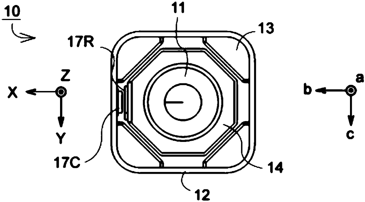
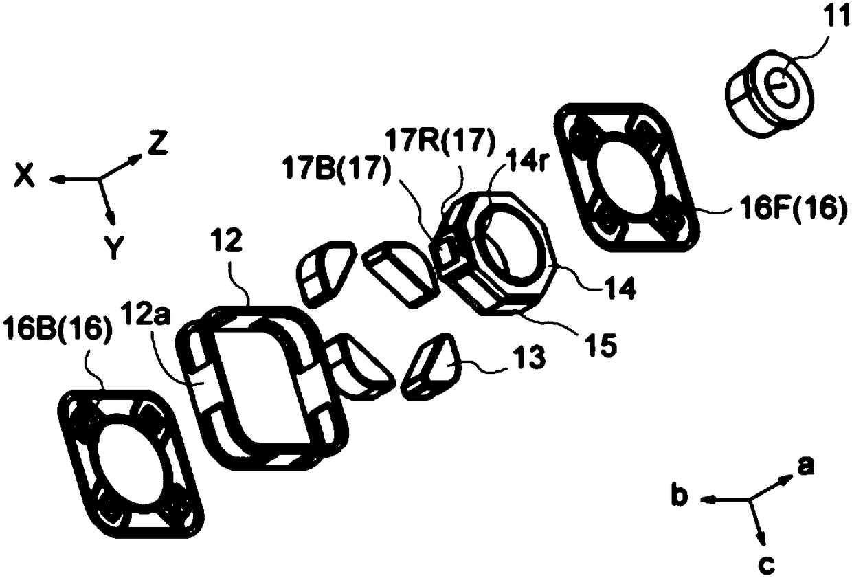
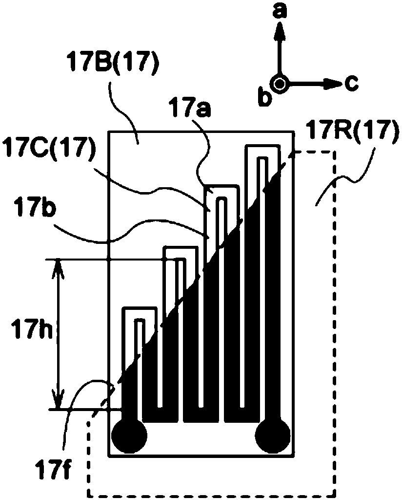
[0035] FIG. 1( a ) is a plan view showing the appearance of main parts of Example 1 of a lens driving device 10 equipped with a position detecting device 17 according to this embodiment, and FIG. 1( b ) is an exploded perspective view. also, Figure 2(a) ~ Figure 2(d) It is a plan view showing the position detection coil 17C and the position detection conductive member 17R included in the position detection device 17 in this embodiment. The position detection coil and the position detection conductive me...


PUM


Abstract

The invention provides a position detecting device, a lens drive device, a camera device, and electronic equipment. The position detecting device is provided with a coil and a conductive part, and thecoil is formed in a plane which takes a direction M perpendicular to a moving direction (a direction L) as the normal direction, and has a curved wiring part. The curved wiring part is provided witha fold-back part formed at an end part, and fold-back width parts which extend from two ends of the fold-back part. The fold-back width parts are respectively provided with direct-entry parts which extend in a parallel manner. The conductive part and the coil are separated by a certain gap in the direction M, and are opposite to each other. Being observed in the direction M, the edge part of the conductive part is set to be opposite to the direct-entry parts of the curved wiring part, and extends in a direction which is not parallel to the extending direction of the direct-entry parts and thedirection L, and laterally passes through the plurality of direct-entry parts. According to the invention, the device can effectively change the size of the coil, is small, and can accurately reflectthe fixed length.

Description

technical field [0001] The present invention relates to a position detection device, a lens driving device including the position detection device, a camera device, and electronic equipment. Background technique [0002] Conventionally, as a position detection device, the structure is such that a substrate with a printed coil is placed parallel to the optical axis on an optical device having a moving frame that fixes a lens and moves in the direction of the optical axis of the lens, and at the same time, A flat conductive member facing the substrate is provided. The conductive member is formed in a trapezoidal shape, so that the width of the projected surface on the coil in the direction perpendicular to the optical axis changes with the position in the direction of the optical axis, and the inductance of the coil changes with the lens moving. For example, in the patent document (Japanese Patent Laid-Open No. 2006-178362 ), the position of the lens is detected according to ...

Claims


Application Information

Patent Timeline
IPC IPC(8): G01B7/00G02B7/04H04N5/225G03B30/00
CPCG01B7/003G02B7/04H04N23/50H04N23/57H04N23/55G02B7/08H02K41/0356G03B3/10G03B2205/0069G01D5/202G03B13/34H02K41/031
Inventor 寺嶋厚吉
Owner NEW SHICOH MOTOR CO LTD
Why Eureka
Try Eureka