Supercharge Your Innovation With Domain-Expert AI Agents!

Novel garbage compression equipment

A technology of garbage compression and equipment, which is applied in the direction of garbage cans, garbage collection, household appliances, etc. It can solve the problems of difficulty in meeting processing requirements, high use cost, and difficult operation, etc., and achieves simple structure, improved service life, and improved safety. Effect

Inactive Publication Date: 2018-05-25
广州快舟智能环保科技有限公司
View PDF4 Cites 0 Cited by
  • Summary
  • Abstract
  • Description
  • Claims
  • Application Information

AI Technical Summary

Problems solved by technology

[0002] In the urban waste recycling station, plastic solid domestic waste such as cans and plastic bottles need to be compressed before processing to reduce the volume. In traditional technology, the compression of waste is generally done by manual extrusion, which is difficult to operate. Moreover, the efficiency is low, and it is difficult to meet the processing needs. There are also many automatic garbage compression devices in the existing industry, but their structures are complex, the cost of use is high, and there are major disadvantages, which need to be improved.

Method used


Image

  • Novel garbage compression equipment
  • Novel garbage compression equipment
  • Novel garbage compression equipment

Examples


Embodiment Construction

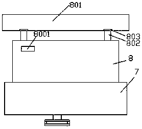
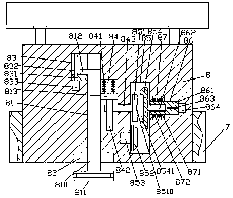
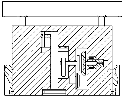
[0014] Such as Figure 1-Figure 4 As shown, a new type of garbage compression equipment of the present invention includes a pedestal 7 and a compressor 8 fixedly installed in the pedestal 7. The compressor 8 is provided with a first sliding joint cavity 81 extending up and down. The bottom of the first sliding connection chamber 81 is extended and connected to the tail with a receiving groove 82, the bottom of the receiving groove 82 passes through the bottom surface of the compressor 8, and the inner wall of the top left side of the first sliding connection chamber 81 is connected with a first guide. Groove 83, the first guide groove 83 is provided with a locking device, and the middle position of the inner wall on the right side of the first sliding connection cavity 81 is connected with a transmission cavity 84, and the compression cavity 84 on the right side of the transmission cavity 84 The machine 8 is provided with an accommodating cavity 85, and the inner wall of the r...


PUM


Abstract

The invention discloses novel garbage compression equipment. The novel garbage compression equipment comprises a pedestal and a compressor fixedly installed in the pedestal. A first sliding connectingcavity arranged in an up-down extending mode is arranged in the compressor. The extending tail portion of the bottom of the first sliding connecting cavity is connected with a containing groove. Thebottom of the containing groove penetrates through the bottom surface of the compressor. A first guide connecting groove is formed in the inner wall of the top of the left side of the first sliding connecting cavity in a communicating mode. A locking connecting device is arranged in the first guide connecting groove. A conveying cavity is arranged in the middle of the inner wall of the right sideof the first sliding connecting cavity in a communicating mode. A containing cavity is arranged in the part, on the right side of the conveying cavity, of the compressor. A second sliding connecting cavity is arranged in the inner wall of the right side of the containing cavity in a communicating mode. A first sliding connecting rod arranged in an up-down extending mode is arranged in the first sliding connecting cavity in a sliding connecting fit mode. The extending tail portion of the top of the first sliding connecting rod extends to the position opposite to the first guide connecting groove. The extending tail portion of the bottom of the first sliding connecting rod extends into the containing groove and is fixedly provided with a compressing plate. The novel garbage compression equipment is simple in structure, realizes efficient garbage compression, improves operation safety, and is prolonged in service life.

Description

technical field [0001] The invention relates to the field of garbage compression, in particular to a novel garbage compression equipment. Background technique [0002] In the urban waste recycling station, plastic solid domestic waste such as cans and plastic bottles need to be compressed before processing to reduce the volume. In traditional technology, the compression of waste is generally done by manual extrusion, which is difficult to operate. Moreover, the efficiency is low, and it is difficult to meet the processing requirements. There are also many automatic garbage compression devices in the existing industry, but their structures are complex, the cost of use is high, and there are major drawbacks, which need to be improved. Contents of the invention [0003] The technical problem to be solved by the present invention is to provide a new type of garbage compression equipment, which can solve the above-mentioned problems in the prior art. [0004] The present inven...

Claims


Application Information

Patent Timeline
IPC IPC(8): B65F1/14
CPCB65F1/1405B65F2210/162
Inventor 余强
Owner 广州快舟智能环保科技有限公司
Features
  • R&D
  • Intellectual Property
  • Life Sciences
  • Materials
  • Tech Scout
  • Unparalleled Data Quality
  • Higher Quality Content
  • 60% Fewer Hallucinations
Learn More