
Lens driving mechanism

A driving mechanism and optical technology, applied in optics, optical components, cameras, etc., can solve problems such as shaking and blurred images, and achieve the effect of saving thickness, reducing volume and improving image quality.

Active Publication Date: 2018-05-25
TDK TAIWAN
View PDF30 Cites 9 Cited by
  • Summary
  • Abstract
  • Description
  • Claims
  • Application Information

AI Technical Summary

Problems solved by technology

When a user uses an electronic device equipped with a lens module, there may be shaking, which may cause blurred images captured by the lens module

Method used


Image

  • Lens driving mechanism
  • Lens driving mechanism
  • Lens driving mechanism

Examples


Embodiment Construction

[0068] The optical driving mechanism of the embodiment of the present invention is described below. It should be readily appreciated, however, that the embodiments of the invention provide many suitable inventive concepts that can be implemented in a wide variety of specific contexts. The specific embodiments disclosed are merely illustrative of specific ways to use the invention and do not limit the scope of the invention.

[0069] Unless otherwise defined, all terms (including technical and scientific terms) used herein have the same meaning as commonly understood by one of ordinary skill in the art to which this disclosure belongs. It is understood that these terms, such as those defined in commonly used dictionaries, should be interpreted as having a meaning consistent with the background or context of the related art and the present disclosure, rather than in an idealized or overly formal manner Interpretation, unless specifically defined herein.

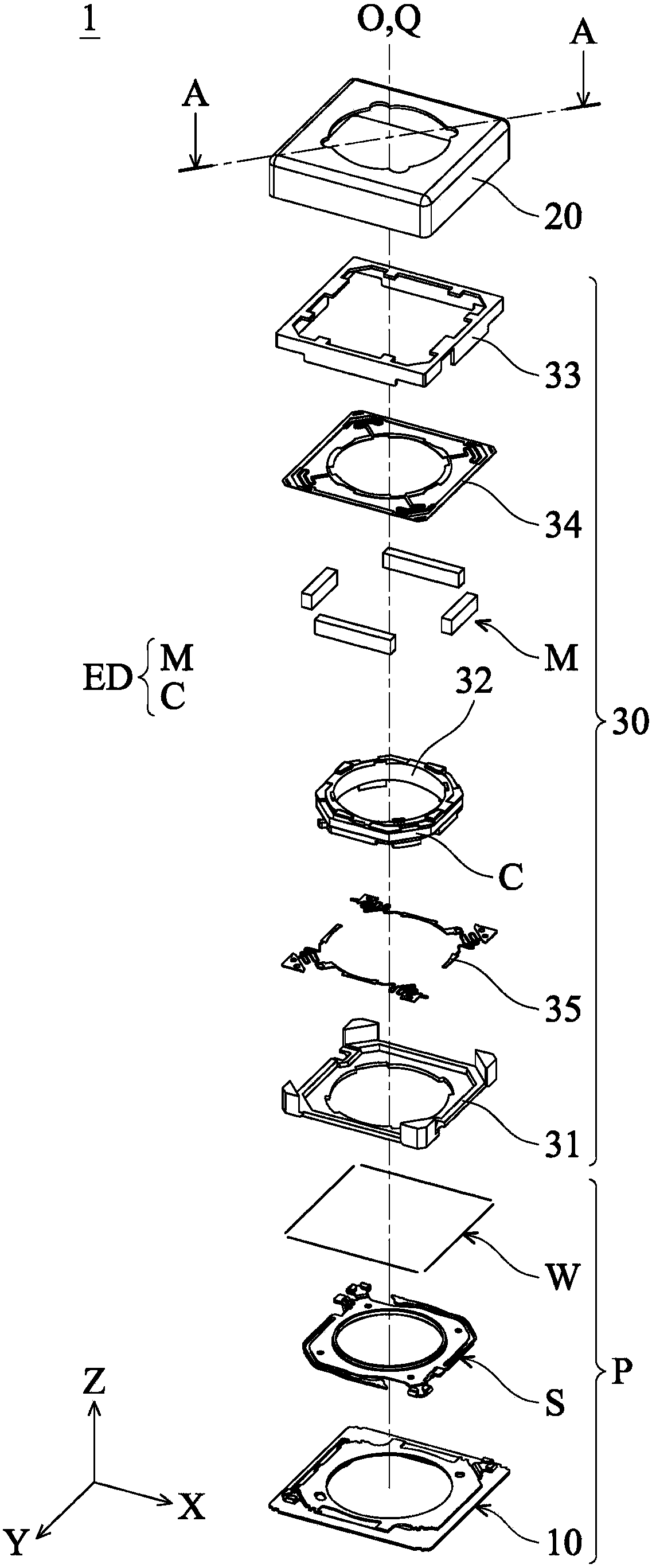
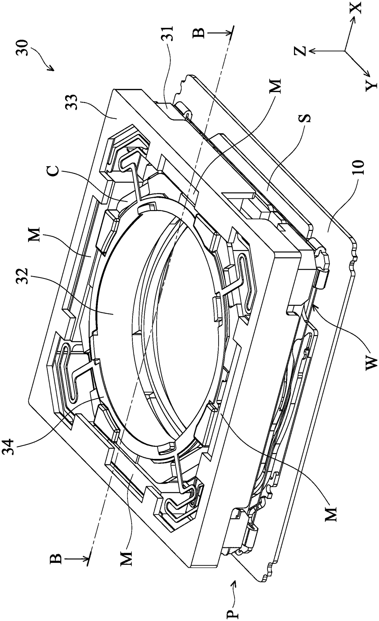
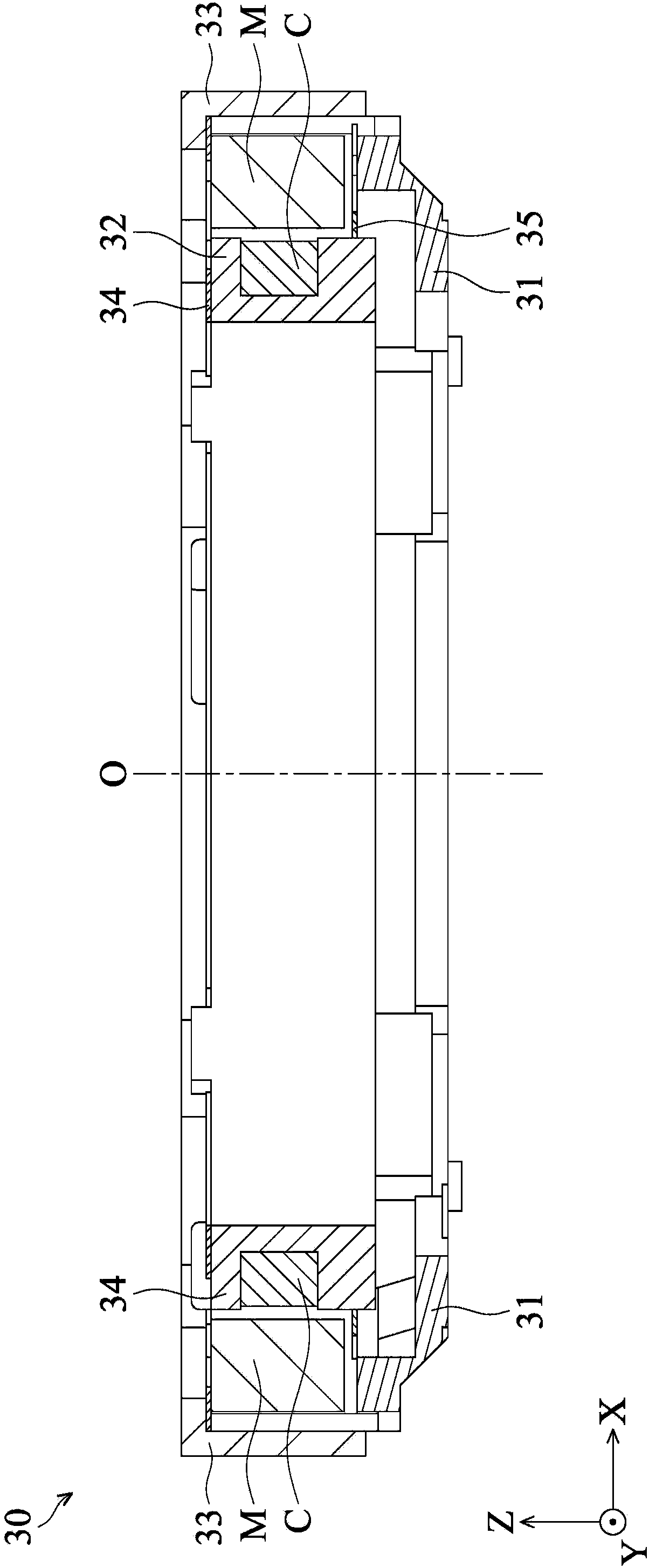
[0070] figure 1 It i...


PUM


Abstract

A lens driving mechanism is provided, configured to drive an optical lens, including a bottom plate, a movable portion, an elastic member, and a biasing assembly. The movable portion is disposed on the bottom plate and has a base and a holder, wherein the holder is configured to hold the optical lens, and the holder is movably connected to the base. The elastic member connects the movable portionto the bottom plate. The biasing assembly connects the bottom plate and the movable portion and is configured to force the movable portion to move relative to the bottom plate. When the holder moves to a lower-limit position relative to the base, the holder comes into contact with the elastic member.

Description

technical field [0001] The invention discloses an optical drive mechanism, in particular to an optical drive mechanism that restricts the movement of a carrier and an optical lens through an outer frame. Background technique [0002] With the development of technology, many electronic devices (such as tablet PCs or smart phones) are miniaturized and equipped with lens modules to have the function of taking pictures or recording videos. When the user uses the electronic device equipped with the lens module, there may be shaking, which makes the image captured by the lens module blurred. Nowadays, people's requirements for high-quality images and miniaturization of electronic products are increasing day by day, which makes electronic products with excellent shockproof function and miniaturized lens modules more and more important. Contents of the invention [0003] The main purpose of the present invention is to provide an optical driving structure so that the optical drivi...

Claims


Application Information

Patent Timeline
IPC IPC(8): G02B7/04G03B5/00G02B7/09
CPCG02B7/04G02B7/09G03B5/00
Inventor 郭侲圻胡朝彰宋欣忠
Owner TDK TAIWAN
Learn More