
Radiators and Radiator Assemblies

A heat sink and heat sink technology, applied in semiconductor devices, electrical solid state devices, semiconductor/solid state device components, etc., can solve problems such as limitations, improve performance and life, improve stability and reliability, and improve heat dissipation efficiency effect

Active Publication Date: 2019-10-11
BYD SEMICON CO LTD
View PDF9 Cites 0 Cited by
  • Summary
  • Abstract
  • Description
  • Claims
  • Application Information

AI Technical Summary

Problems solved by technology

[0002] The radiator in the existing radiator assembly enters water from one end, and the water path flows to the heat sink, and passes through the power device to be dissipated successively. Along the flow direction of the water path, the temperature drop of the power device to be dissipated will gradually decrease, which will cause the water path to The temperature of the most downstream power device is much higher than that of the most upstream power device. As the number of power devices to be dissipated increases, the temperature difference will be greater, and the temperature of the most downstream power device will also be higher. The performance of the entire product and lifetime will be limited by the power device

Method used


Image

  • Radiators and Radiator Assemblies
  • Radiators and Radiator Assemblies
  • Radiators and Radiator Assemblies

Examples


Embodiment Construction

[0026] Embodiments of the present invention are described in detail below, examples of which are shown in the drawings, wherein the same or similar reference numerals designate the same or similar elements or elements having the same or similar functions throughout. The embodiments described below by referring to the figures are exemplary and are intended to explain the present invention and should not be construed as limiting the present invention.

[0027] In describing the present invention, it should be understood that the terms "longitudinal", "transverse", "length", "width", "thickness", "upper", "lower", "front", "rear", " The orientation or positional relationship indicated by "left", "right", "vertical", "horizontal", "top", "bottom", "inner", "outer", etc. is based on the orientation or positional relationship shown in the drawings, It is only for the convenience of describing the present invention and simplifying the description, but does not indicate or imply that ...


PUM


Abstract

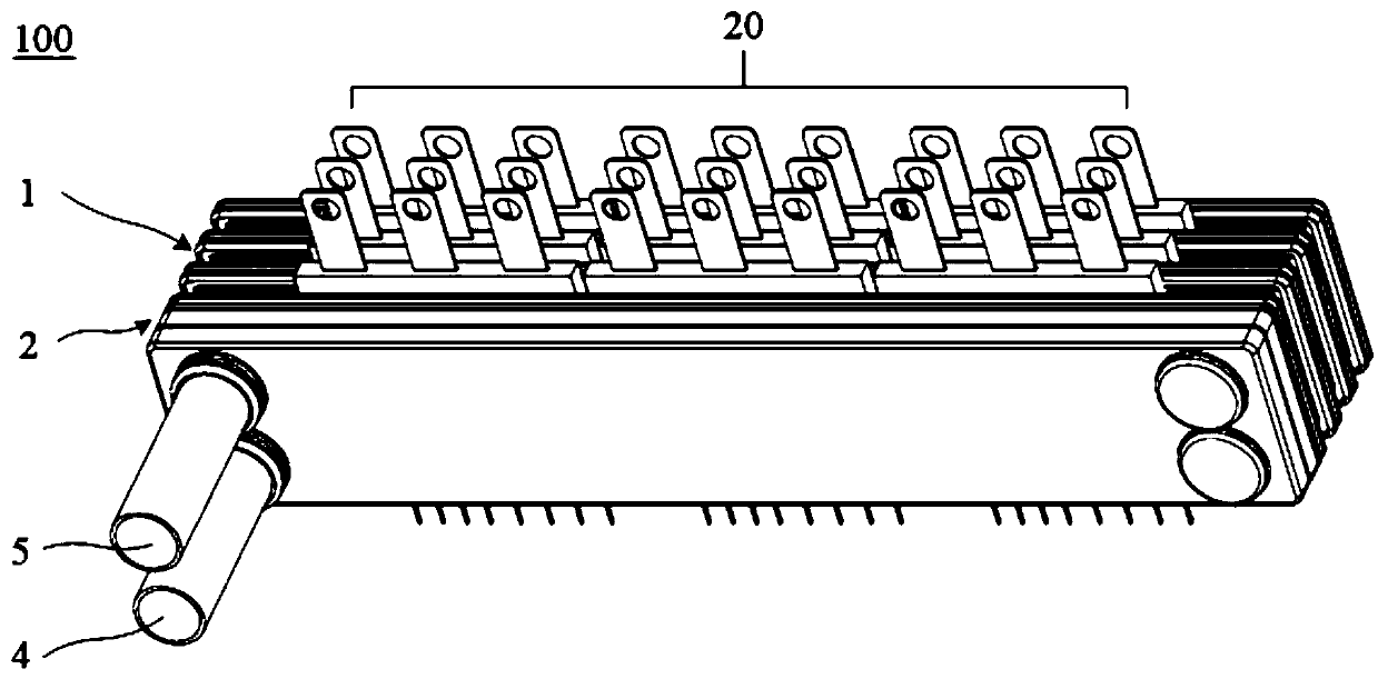
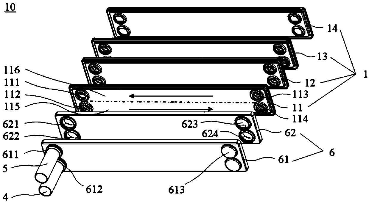
The invention discloses a radiator and a radiator component. The radiator comprises multiple cooling fins, wherein a to-be-radiated power device is suitably clamped between any two adjacent cooling fins, and a first water channel and a second water channel which are separated from each other are arranged in each cooling fin; a first flow leader; a second flow leader; a main water inlet pipe, wherein the main water inlet pipe is communicated with an inlet of each first water channel, and the main water inlet pipe is communicated with the inlet of each second water channel through the first flowleader; a main water outlet pipe, wherein the main water outlet pips is communicated with an outlet of each first water channel, and the main water outlet pipe is communicated with the outlet of eachsecond water channel through the second flow leader; and a heat transferring medium, wherein a flowing direction of the heat transferring medium at the first water channel is opposite to the flowingdirection at the second water channel. According to the radiator disclosed by the embodiment of the invention, the two-way flowing of the heat transferring medium in the first water channel and the second water channel is guaranteed through the first flow leader and the second flow leader, thereby effectively balancing the temperature difference of the to-be-radiated devices and improving the performance and service life of the radiator component.

Description

technical field [0001] The invention relates to the field of automobiles, in particular to a radiator and a radiator assembly. Background technique [0002] The radiator in the existing radiator assembly enters water from one end, and the water path flows to the heat sink, and passes through the power device to be dissipated successively. Along the flow direction of the water path, the temperature drop of the power device to be dissipated will gradually decrease, which will cause the water path to The temperature of the most downstream power device is much higher than that of the most upstream power device. As the number of power devices to be dissipated increases, the temperature difference will be greater, and the temperature of the most downstream power device will also be higher. The performance of the entire product and lifetime will be limited by this power device. Contents of the invention [0003] The present invention aims to solve one of the above-mentioned tech...

Claims


Application Information

Patent Timeline
Patent Type & Authority Patents(China)
IPC IPC(8): H01L23/473
CPCH01L23/473
Inventor 杨小华陈银严百强
Owner BYD SEMICON CO LTD
Learn More