
Electrical Connectors and Terminals

A technology of electrical connectors and terminals, which is applied in the direction of connection, fixed connection, and parts of connection devices, can solve problems such as difficult manufacturing and complex overall structure, and achieve the goal of not being warped and deformed, avoiding empty welding, and ensuring empty welding Effect

Active Publication Date: 2020-06-05
MOLEX INC
View PDF11 Cites 0 Cited by
  • Summary
  • Abstract
  • Description
  • Claims
  • Application Information

AI Technical Summary

Problems solved by technology

In addition to the first and second sliding slots, the first side arm is also provided with two guide slots for the electronic card to be inserted and a receiving part for accommodating the second side arm, thus making the whole of the first body Complex structure, less easy to manufacture

Method used


Image

  • Electrical Connectors and Terminals
  • Electrical Connectors and Terminals
  • Electrical Connectors and Terminals

Examples


Embodiment Construction

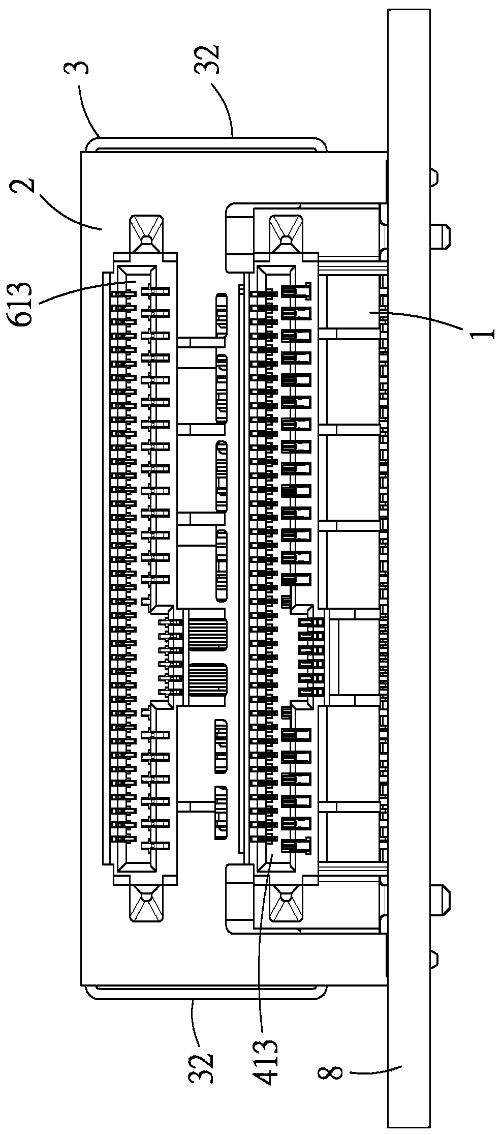
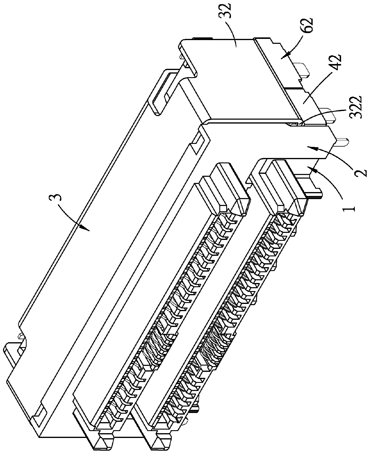
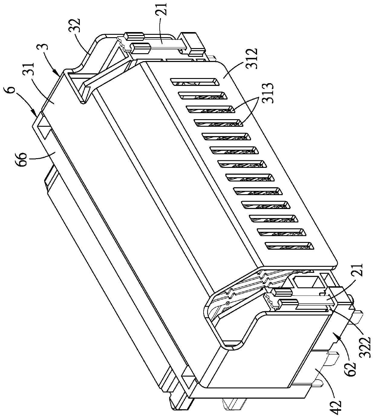
[0105] refer to Figure 1 to Figure 3 , an embodiment of the electrical connector of the present invention is used for mounting on a circuit board 8 by surface soldering. refer to Figure 2 to Figure 5 , the electrical connector includes a first socket unit 1 , a second socket unit 2 and a metal cover 3 .

[0106] see also Figure 6 and Figure 7 , the first socket unit 1 includes a first insulating shell 4 and a plurality of first terminals 5 disposed on the first insulating shell 4 . The first insulating shell 4 has a first body 41 provided with a plurality of first terminals 5 and two first side portions 42 respectively located on the left and right sides, and each first side portion 42 has a direction facing a left and right direction. The first outer surface 421 of X and a first elongated groove 422 concaved from the first outer surface 421 and extending along a front-back direction Y are formed. The first body 41 has a first base portion 411 and a first docking port...


PUM


Abstract

The invention provides an electric connector and a terminal. The electric connector includes a first socket unit, a second socket unit which superposes above and behind the first socket unit and alsoa metal cover. The first socket unit includes a first insulating housing and a plurality of first terminals. The first insulating housing is provided with two first side parts which are arranged on the left and right sides, and each first side part is provided with a first groove. The second socket unit includes a second insulating housing and a plurality of second terminals. The second insulatinghousing is provided with two second side parts which are arranged on the left and right sides, each second side part is provided with a second groove, and the two grooves separately correspond to thetwo first grooves in the forward and backward direction. The metal cover includes a main cover body and two side cover bodies which are separately disposed on the left and right sides, each side cover body is provided with a pad part which is connected to the main cover body and a limiting part which bends and extends from the bottom end of the pad part and extends to the first groove and the second groove on the corresponding side, and the limiting part can float inside the corresponding first groove and the second groove in the up and down direction.

Description

technical field [0001] The invention relates to an electrical connector, in particular to an electrical connector and a terminal capable of simultaneously inserting two electronic cards. Background technique [0002] Generally, an electrical connector that can be inserted into two electronic cards at the same time usually has two slots arranged up and down. If multiple terminals are to be soldered to the circuit board by surface soldering, it is also prone to the problem that the tails of the multiple terminals are not all coplanar, resulting in the problem of empty soldering of some terminals. [0003] There is an existing electrical connector, such as disclosed in Taiwan Patent No. M368946 (Chinese corresponding case CN201397923, American corresponding case US7931495), which includes a first connecting seat, a second connecting seat and a return card. The first connecting seat and the second connecting seat are movably positioned to solve the problem that the terminals ar...

Claims


Application Information

Patent Timeline
Patent Type & Authority Patents(China)
IPC IPC(8): H01R13/502H01R13/02H01R12/57H01R12/72H01R27/02
CPCH01R12/57H01R12/721H01R13/02H01R13/502H01R27/02
Inventor 吴云山
Owner MOLEX INC
Learn More