
Integrated circuit with reverse current detection and power source disconnection detection

An integrated circuit and circuit technology, applied in battery disconnection circuits, safety/protection circuits, emergency protection circuit devices, etc., can solve the problems that the current sensing circuit cannot accurately detect the current level of the input signal, difficulty, and difficult matching of transistors

Active Publication Date: 2018-05-25
NXP BV
View PDF6 Cites 3 Cited by
  • Summary
  • Abstract
  • Description
  • Claims
  • Application Information

AI Technical Summary

Problems solved by technology

Thus, it is difficult to determine the disconnection status between the power source and the load
Further, due to the small voltage difference between the input port and the output port, the transistors of the current sensing circuit are not easily matched with each other, which will reduce the accuracy of the current sensing circuit
Therefore, it is inaccurate and difficult to detect the negative current through the current sensing circuit
In addition, the current sensing circuit cannot accurately detect the current level of the input signal when the current level of the input signal is lower than a threshold

Method used


Image

  • Integrated circuit with reverse current detection and power source disconnection detection
  • Integrated circuit with reverse current detection and power source disconnection detection
  • Integrated circuit with reverse current detection and power source disconnection detection

Examples


Embodiment Construction

[0014] The detailed description with respect to the drawings is intended as a description of presently preferred embodiments of the invention and is not intended to represent the only form in which the invention may be embodied. It is to be understood that the same or equivalent function may be accomplished by different embodiments encompassed within the spirit and scope of the invention.

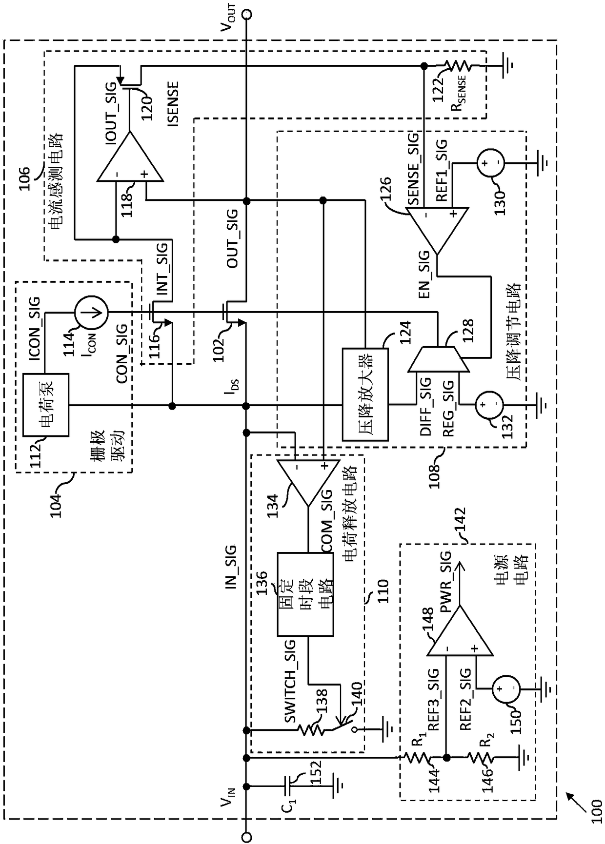
[0015] now turn figure 1 , which shows a block diagram of an integrated circuit 100 according to one embodiment of the present invention. The IC100 is a load switch typically used in battery charging circuits. The IC 100 has an input port connected to a power source (not shown), and an output port connected to a battery (not shown). The IC 100 includes a switching transistor 102 , a gate drive circuit 104 , a current sense 106 , a voltage drop regulation circuit 108 , and a charge discharge circuit 110 .

[0016] The switching transistor 102 has a source and a drain, which are the input ...


PUM


Abstract

An integrated circuit (IC) comprises a switch transistor, a gate driving circuit, a currents sensing circuit, a voltage drop adjusting circuit and a charge release circuit. The switch transistor is connected between an input port and an output port of the IC, receives an input signal from a power supply, and provides the input signal, as an output signal, for an output port; the current sensing circuit detects a current through the switch transistor; the grate driving circuit uses a control signal to drive the switch transistor; when the current through the switch transistor is low, the voltage drop adjusting circuit is activated; the voltage drop adjusting circuit controls the control signal to increase the voltage of the switch transistor; and when the power supply is disconnected, the charge release circuit transfer superfluous charges in the input end of the IC to the ground.

Description

technical field [0001] The invention relates to an integrated circuit, in particular to a load switch of the integrated circuit. Background technique [0002] Load switches are used in electronic circuits to connect or disconnect a power source to or from a load. Load switches are commonly used in battery charging circuits to charge a battery connected as a load. Typically, a load switch has an input port for receiving an input signal from a power source and an output port for connection to a battery. The load switch provides an input signal as an output signal to the battery through an output port to charge the battery. Load switches consist of transistors connected between input and output ports. When the power supply is disconnected and the load switch is still active, it has a very low resistance, on the order of tens of milliohms. This resistance is called "ON resistance". Because of this low "on resistance," the battery will supply a negative current to the load s...

Claims


Application Information

Patent Timeline
Patent Type & Authority Applications(China)
IPC IPC(8): H02H11/00G01R31/04G01R31/40
CPCG01R31/40H02H11/00G01R31/67H02J7/0031H02H3/18G01R19/0092H02H7/1213H02M3/33507H02M3/33592
Inventor 段新东恽廷华卿健
Owner NXP BV
Learn More