
Injection mould capable of accelerating cooling demoulding of injection molding product and working method of injection mould

A technology for injection molding products and injection molds, applied in the field of injection molding machines, can solve the problems of slow cooling speed, inconsistent cooling effect, deformation of injection molding products, etc. Effect

Pending Publication Date: 2018-05-29
太仓朗盛金属制品有限公司
View PDF8 Cites 4 Cited by
  • Summary
  • Abstract
  • Description
  • Claims
  • Application Information

AI Technical Summary

Problems solved by technology

During injection molding, the processing of the shape of the article is mainly realized through the change of the physical state of the molding material. During injection molding, the mold is clamped on the injection molding machine, and the molten plastic is injected into the molding cavity, and is cooled and shaped in the cavity, and then the upper and lower molds Separated, the product is ejected from the mold cavity and leaves the mold through the product ejection mechanism. However, during the cooling process of the existing injection molded products, affected by the depth of the mold cavity, the part inside the molding cavity cannot contact the outside air, and the cooling speed Slow, causing the cooling effect of the same injection molded product to be inconsistent, resulting in the deformation of the injection molded product when the injection molded product is demolded

Method used


Image

  • Injection mould capable of accelerating cooling demoulding of injection molding product and working method of injection mould

Examples


Embodiment Construction

[0018] The present invention will be further explained below in conjunction with the accompanying drawings and specific embodiments.

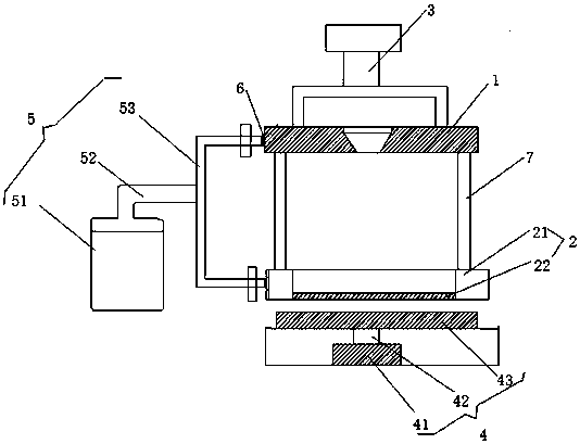
[0019] Such as figure 1 Shown is a kind of injection mold that can accelerate the cooling and demoulding of injection molded products, upper mold base 1, lower mold base 2, clamping oil cylinder 3, product ejection mechanism 4 and air blowing cooling device 5, described clamping oil cylinder 3 and The upper mold base 3 is connected, the lower mold base 2 includes a lower mold base frame body 21 and a bottom bracket 22, the lower mold base frame body 21 and the bottom bracket 22 are flexibly connected, and the product ejection mechanism 4 is arranged at the bottom of the lower mold base 2 Wherein the upper mold base 1 and the lower mold base 2 are provided with internal cooling passages, and the left end of the upper mold base and the lower mold base is provided with a cold air inlet 6, and the cold air inlet 6 is connected with the blowing cool...


PUM


Abstract

The invention discloses an injection mould capable of accelerating cooling demoulding of an injection molding product and a working method of the injection mould. The injection mould comprises an upper mould seat, a lower mould seat, a mould closing air cylinder, a product jacking mechanism and a blowing cooling device; the mould closing air cylinder is connected with the upper mould seat; the lower mould seat comprises a lower mould seat frame and a bottom support which are movably connected; the product jacking mechanism is arranged at the bottom of the lower mould seat; inner cooling channels are formed in the upper mould seat and the lower mould seat correspondingly; and cool air inlets are formed in the left ends of the upper mould seat and the lower mould seat, and the cool air inlets are connected with the blowing cooling device through pipelines. The blowing cooling device can conduct blowing cooling on the upper mould seat and the lower mould seat simultaneously, the speed ofdemoulding of the injection molding product from the upper mould seat and the lower mould seat is increased, and the injection molding demoulding efficiency is improved.

Description

technical field [0001] The invention relates to the technical field of injection molding machines, in particular to an injection mold capable of accelerating cooling and demoulding of injection molding products and a working method thereof. Background technique [0002] Injection mold is a tool for producing plastic products, and it is also a tool for giving plastic products a complete structure and precise dimensions. It is used in industrial production for injection molding, blow molding, extrusion, die-casting or stamping. Due to the variety of plastics and processing methods, and the structure of plastic molding machines and plastic products, the types and structures of plastic molds are also diverse. During injection molding, the processing of the shape of the article is mainly achieved through the change of the physical state of the molding material. During injection molding, the mold is clamped on the injection molding machine, and the molten plastic is injected into ...

Claims


Application Information

Patent Timeline
Patent Type & Authority Applications(China)
IPC IPC(8): B29C45/40B29C45/73
CPCB29C45/4005B29C45/7337
Inventor 夏继文
Owner 太仓朗盛金属制品有限公司
Learn More