Three-dimensional zero-gravity simulation device combining knife cam constant-force spring and air thrust bearing

A technology of constant force springs and thrust bearings, applied in the field of three-dimensional zero-gravity simulation devices, can solve the problems of high aircraft handling and maintenance costs, and affect the accuracy of aircraft microgravity simulation, and achieve simple structure, easy maintenance, and low processing costs Effect

Active Publication Date: 2018-05-29
HARBIN INST OF TECH
View PDF8 Cites 4 Cited by
  • Summary
  • Abstract
  • Description
  • Claims
  • Application Information

AI Technical Summary

Problems solved by technology

[0006] The present invention aims to solve the problem that existing space microgravity simulation methods and devices have friction or resistance

Method used


Image

  • Three-dimensional zero-gravity simulation device combining knife cam constant-force spring and air thrust bearing

Examples


specific Embodiment approach 1

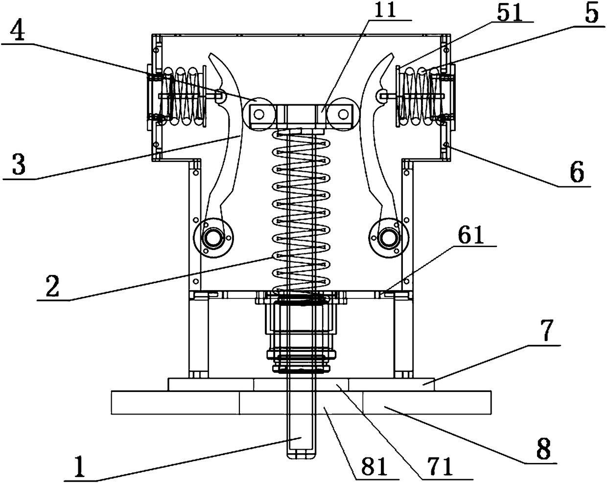
[0019] A three-dimensional zero-gravity simulation device combined with a knife-type cam constant force spring and an air-floating thrust bearing, including: a positive and negative rigidity combined spring assembly, an inverted plane air foot 7 and an air-floating support plate 8;

[0020] The center of the plane air foot 7 is provided with an air foot plate through hole 71, and the center of the air flotation supporting plate 8 is provided with a supporting plate through hole 81; the plane air foot 7 is provided with several throttle holes, and the plane air foot 7 is provided with an air cavity, after the air supply, the compressed gas flows out from the orifice, forming a high-rigidity air film between the plane air foot and the air flotation support plate, and the plane air foot 7 and the air flotation support plate 8 work together to realize the plane air foot 7 Ultra-low-friction air suspension lubrication between the air bearing plate 8 and two-dimensional zero-gravity ...

specific Embodiment approach 2

[0030] In this embodiment, the plane air foot 7 is provided with 8 throttle holes.

[0031] Other structures and parameters are the same as those in the first embodiment.

specific Embodiment approach 3

[0032] The diameter of the orifice in this embodiment is 0.2 mm.

[0033] Other structures and parameters are the same as those in Embodiment 1 or Embodiment 2.


PUM

PropertyMeasurementUnit
Diameteraaaaaaaaaa
Diameteraaaaaaaaaa

Abstract

The invention provides a three-dimensional zero-gravity simulation device combining a knife cam constant-force spring and an air thrust bearing and relates to a three-dimensional zero-gravity simulation device. The three-dimensional zero-gravity simulation device combining the knife cam constant-force spring and the air thrust bearing is to solve a problem that the aircraft microgravity simulationaccuracy is affected by friction, resistance or turbulent flow in the existing space microgravity simulation method and device. An air film can be formed between a plane air foot and an air supporting plate; a housing is arranged on the plane air foot; two horizontal springs are symmetrically arranged on the internal side wall of the housing; one ends of two knife cams are symmetrically arrangedon the internal side wall of the housing through hinging pieces; the other ends or middle parts of the two knife cams are connected with the two horizontal springs through hinges and connecting pieces; a bearing spindle is connected with a roller arm; rollers are respectively arranged at the two ends of the roller arm; the two rollers are respectively in contact with the arch back parts of the twoknife cams; a vertical main spring sleeves the bearing spindle; and the two ends of the vertical main spring respectively prop against the roller arm and a spring partition plate. The three-dimensional zero-gravity simulation device combining the knife cam constant-force spring and the air thrust bearing is applicable to aircraft three-dimensional zero-gravity simulation tests.

Description

technical field [0001] The invention relates to a three-dimensional zero-gravity simulation device. Background technique [0002] Due to the huge cost of space experiments, generally before the space vehicle experiment, in order to ensure the normal operation of various equipment after lift-off and meet the required performance indicators, a lot of pre-research must be carried out on the ground before lift-off. Space microgravity simulation is a new field that has emerged with the development of space technology, and has become one of the main technologies that the space powers have successively paid attention to. After decades of development, the drop tower method and the suspension method have successively appeared. , water flotation and air flotation, etc., microgravity experiments. [0003] The drop tower method is not only expensive, but also the size of the spacecraft is limited and its versatility is poor. More importantly, the time of a single microgravity experimen...

Claims


Application Information

Patent Timeline
IPC IPC(8): B64G7/00
CPCB64G7/00
Inventor 霍明英曹世磊孙俊朱东方齐乃明刘延芳杨曼唐梦莹
Owner HARBIN INST OF TECH
Why Eureka
Try Eureka