
Heat dissipating system and vehicle lamp

A heat dissipation system and heat dissipation device technology, applied in the direction of headlights, motor vehicles, road vehicles, etc., can solve the problems of poor heat dissipation effect of the heat dissipation system, and achieve the effects of improving heat dissipation effect, enhancing air flow, and accelerating air flow

Inactive Publication Date: 2018-05-29
HASCO VISION TECHNOLOGY CO LTD
View PDF10 Cites 6 Cited by
  • Summary
  • Abstract
  • Description
  • Claims
  • Application Information

AI Technical Summary

Problems solved by technology

[0005] The purpose of the present invention is to provide a heat dissipation system to solve the technical problem of the poor heat dissipation effect of the heat dissipation system in the prior art

Method used


Image

  • Heat dissipating system and vehicle lamp
  • Heat dissipating system and vehicle lamp
  • Heat dissipating system and vehicle lamp

Examples


Embodiment 1

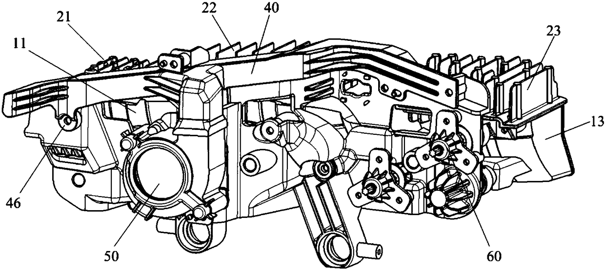
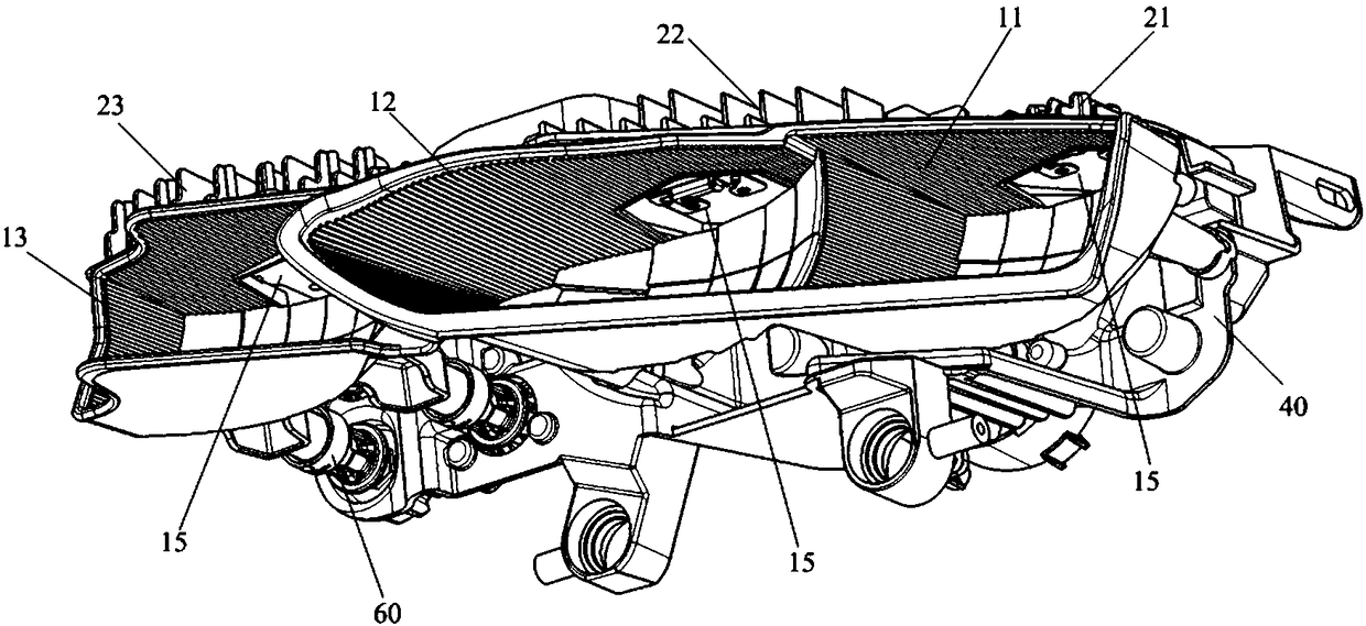
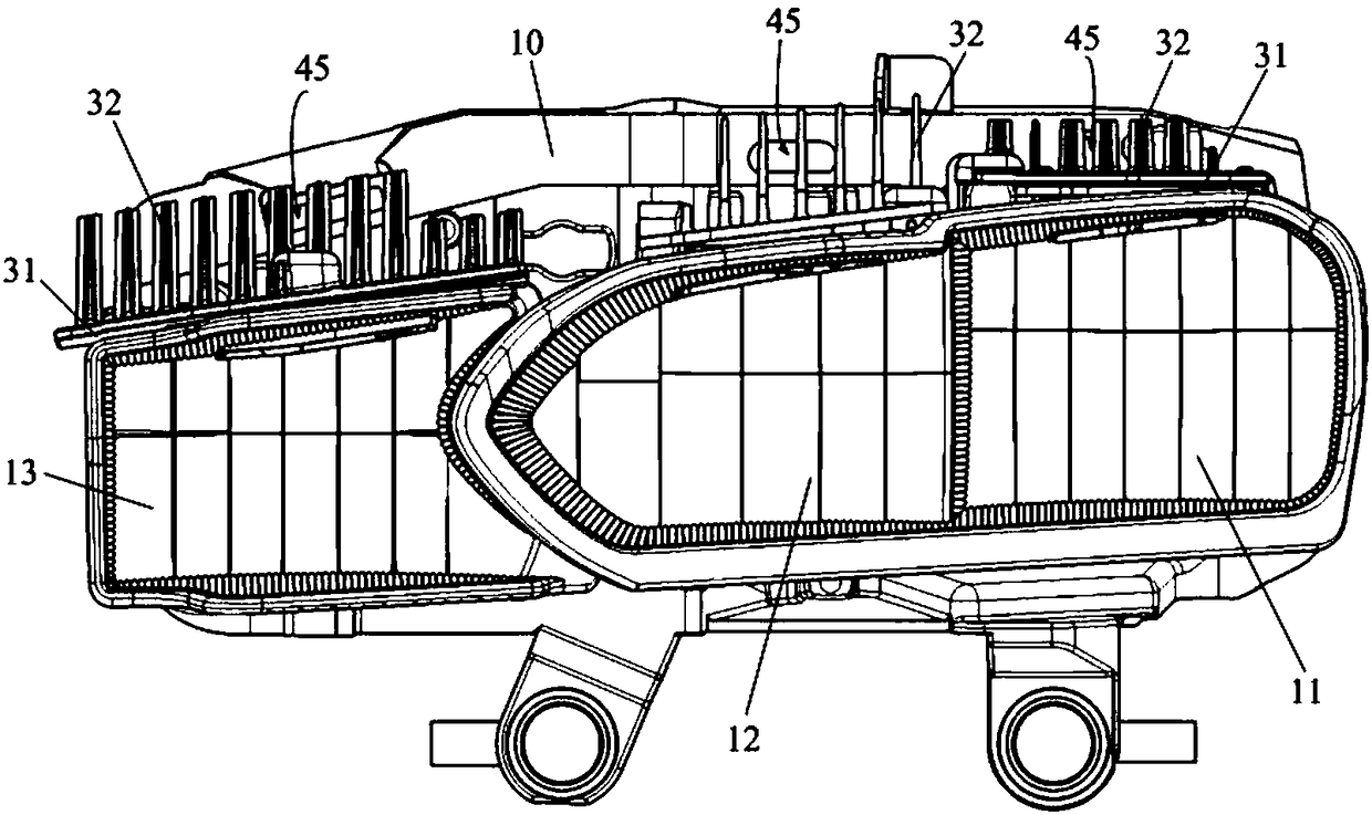
[0046] Such as Figure 1-5 As shown, the heat dissipation system provided by the embodiment of the present invention includes: an air guiding pipeline 40, an air supply device 50, and a main low beam heat dissipation device 21 respectively installed on the main low beam reflector 11, and a main low beam heat dissipation device 21 installed on the auxiliary low beam reflector The auxiliary low beam cooling device 22 on the 12 and the high beam cooling device 23 installed on the high beam reflector 13. Wherein, the air outlet of the air supply device 50 communicates with the air inlet 44 of the air guiding pipeline 40, and the air outlet 45 of the air guiding pipeline 40 faces the main low beam cooling device 21, the auxiliary low beam cooling device 22 and the high beam cooling device respectively. twenty three.

[0047] During the use of the heat dissipation system provided by the embodiment of the present invention, the main low beam heat dissipation device 21 dissipates heat ...

Embodiment 2

[0064] Embodiment 2 of the present invention provides a vehicle lamp, including: a main low beam reflector, an auxiliary low beam reflector, a high beam reflector, and the heat dissipation system provided in Embodiment 1 above. In the heat dissipation system, the main low beam heat dissipation device is installed on the main On the low beam reflector, the auxiliary low beam cooling device is installed on the auxiliary low beam reflector, and the high beam cooling device is installed on the high beam reflector.

[0065] During specific implementation, the air guide pipeline in the cooling system is connected to the main low beam reflector, auxiliary low beam reflector and high beam reflector, and the main low beam reflector, auxiliary low beam reflector and high beam reflector are all connected to each other. Mounting holes are provided, and LED chips are respectively arranged in the mounting holes, and the LED chips are connected with the corresponding main low beam cooling dev...


PUM


Abstract

The invention provides a heat dissipating system and a vehicle lamp, relates to the technical field of vehicle lamps, and solves the problem of weaker heat dissipating effect in a traditional heat dissipating system. The heat dissipating system comprises a wind guide pipeline, a wind supply device, a main near light heat dissipating device mounted on a main near light reflecting mirror, an auxiliary near light heat dissipating device mounted on an auxiliary near light reflecting mirror, and a far light heat dissipating device mounted on a far light reflecting mirror; a wind outlet of the windsupply device communicates with a wind inlet of the wind guide pipeline; and a wind outlet of the wind guide pipeline is towards the main near light heat dissipating device, the auxiliary near light heat dissipating device and the far light heat dissipating device. The heat dissipating system is applied to the vehicle lamp; the wind supply device conveys wind to the main near light heat dissipating device, the auxiliary near light heat dissipating device and the far light heat dissipating device through the wind guide pipeline, so that air flowing is accelerated, and the heat dissipating effect is excellent.

Description

technical field [0001] The invention relates to the technical field of vehicle lamps, in particular to a cooling system and a vehicle lamp. Background technique [0002] Because LED (Light Emitting Diode, light-emitting diode) has the characteristics of high brightness, rich colors, low power consumption, and long life, LEDs are widely used as light sources in current car lights. LEDs generate high heat when they work, and must be used The heat dissipation system dissipates heat for it. [0003] In current automobile lamps, a heat sink is usually used to dissipate heat for the LED light source. Specifically, the aluminum substrate of the LED light source is connected to the heat sink, and the heat sink is installed on the reflector. The heat sink includes heat sinks, and the heat dissipation area is increased through the heat sinks so as to improve the heat dissipation effect. If you want to improve the heat dissipation effect, you need to increase the volume of the heat s...

Claims


Application Information

Patent Timeline
IPC IPC(8): F21S45/43F21S45/49F21S41/141F21S41/36F21S41/675F21Y115/10F21W107/10F21W102/13
CPCF21Y2115/10F21S41/39F21S45/435
Inventor 陈现
Owner HASCO VISION TECHNOLOGY CO LTD
Learn More