[0031] The present invention will be further described in detail below in conjunction with embodiments, but the protection scope of the present invention is not limited thereto.
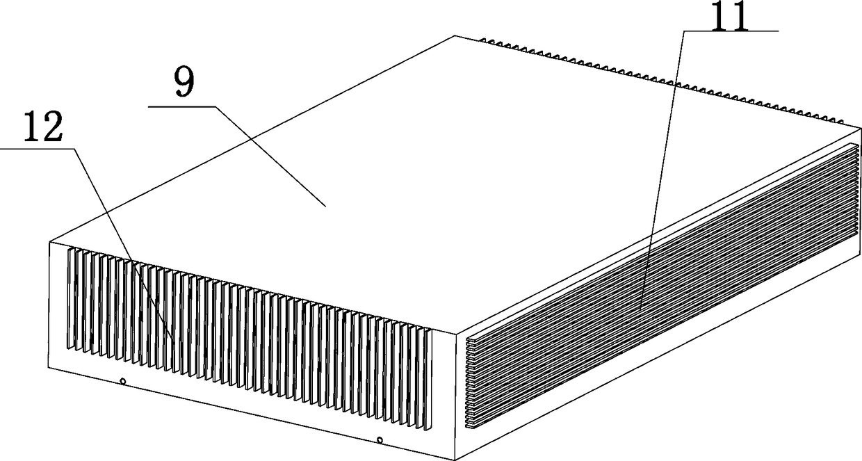
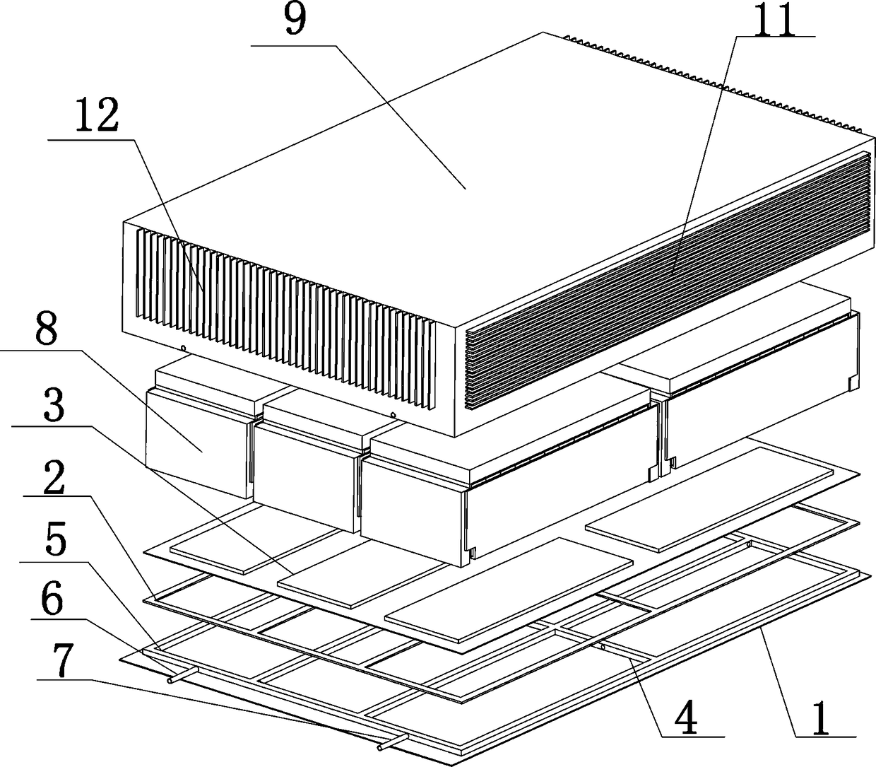
[0032] The present invention relates to an integrated cooling and heat preservation battery system, comprising a battery box body, the battery box body includes a lower box body, the lower box body includes a lower box cover 1 and a heat insulation layer 2 arranged sequentially from bottom to top And the heat conducting plate 3, the lower box cover 1 is provided with a tank body 4, the tank body 4 and the heat insulation layer 2 are set as a closed flow channel 5, the outlet 6 of the flow channel 5 and the flow channel 5 The inlets 7 are respectively arranged on the sides of the lower box body; the heat conducting plate 3 is provided with a battery module block 8, and the lower box body outside the battery module block 8 is matched with an upper box body 9; the battery The module block 8 is matched with a number of temperature sensors, which are respectively connected to a controller, and the controller is connected to an external temperature control mechanism. Both ends of the external temperature control mechanism are respectively connected to the flow through the pipeline 10 The outlet 6 of the channel 5 and the inlet 7 of the flow channel 5.
[0033] In the present invention, the battery system includes a battery box. The battery box includes a lower box and an upper box 9. The upper box 9 and the lower box cooperate to form an integral battery box, and the battery box is provided with a battery module block 8 , Complete the charge and discharge of the battery system.
[0034] In the present invention, the lower box body includes a lower box cover 1, an insulating layer 2 and a heat conducting plate 3 which are sequentially arranged from bottom to top. The lower box cover 1, the heat insulating layer 2 and the heat conducting plate 3 are arranged in cooperation, and the lower box cover 1 A trough 4 is provided on the top to form the lower half of the flow channel 5. The heat insulation layer 2 and the heat conducting plate 3 form the upper half of the flow channel 5. The trough 4, the heat insulation layer 2 and the heat conducting plate 3 are matched to be closed 的流道5.
[0035] In the present invention, the flow channel 5 is used to pass in and out the cooling liquid, and the temperature of different battery module blocks 8 is used to complete different thermal management modes. The outlet 6 of the flow channel 5 and the inlet 7 of the flow channel 5 are respectively arranged below The side of the box.
[0036] In the present invention, in actual work, a number of temperature sensors are used to obtain the temperature of the battery module block 8, which is fed back to the controller, and the controller passes the external temperature control mechanism through the pipeline 10 to the outlet 6 and the flow channel 5 The inlet 7 of the channel 5 enters or discharges the cooling liquid and evacuates the flow channel 5 to perform thermal management of the battery system such as heat preservation, natural cooling or liquid cooling.
[0037] The invention uses cooling liquid and vacuum as media through the establishment/blocking technology of heat conduction path to easily reconcile the contradiction between heat preservation, natural cooling and liquid cooling, so that the thermal management subsystem can freely operate in three thermal management modes Switch, so as to minimize the energy consumption of thermal management under the premise of ensuring good thermal management. When applied to vehicles, it can improve the endurance of the entire vehicle.
[0038] The upper box 9 includes a rectangular top cover, four sides of the top cover are vertically downwardly provided with a left side panel, a front side panel, a right side panel, and a rear side panel, the left side panel, the front side panel , The right side panel and the rear side panel are connected end to end, the rectangular top cover, the left side panel, the front side panel, the right side panel and the rear side panel are integrally arranged; the lower box cover 1 of the lower box body is rectangular.
[0039] The left side plate, the front side plate, the right side plate and the rear side plate are provided with fins; the left side plate and the right side plate are provided with transverse fins 11; the front side plate and the rear side plate With longitudinal fins 12.
[0040] In the present invention, in general, for the convenience of installation, the battery box is configured as a cube or cuboid as a whole, that is, the top cover of the upper box 9 is rectangular. In actual operation, the lower box is surrounded by side panels or at least Shallow ribs, the upper box body 9 and the lower box body are coordinated.
[0041] In the present invention, the upper box body 9 includes a left side panel, a front side panel, a right side panel and a rear side panel connected end to end. The left side panel, the front side panel, the right side panel and the rear side panel are all provided with fins, Used for heat dissipation.
[0042] In the present invention, the fins are composed of horizontal fins 11 and longitudinal fins 12, wherein the horizontal fins 11 rely on relative movement with the ambient air during driving to strengthen convective heat transfer and dissipate heat into the ambient air, while the longitudinal fins 11 12 Dissipate heat into the ambient air by natural convection.
[0043] The battery module block 8 includes a plurality of battery modules arranged in an array; the plurality of temperature sensors are arranged in a one-to-one correspondence with the battery modules.
[0044] The heat insulation layer 2 includes a plurality of heat insulation frames, the plurality of heat insulation frames are arranged in an array, and the heat insulation frames are arranged in a one-to-one correspondence with the battery modules.
[0045] A number of thermally conductive pads are arranged between the thermally conductive plate 3 and the battery module block 8, the thermally conductive pads are arranged in an array, and the thermally conductive pads and the battery modules are arranged in a one-to-one correspondence.
[0046] In the present invention, the battery module block 8 is composed of a number of battery modules arranged in an array. Therefore, a number of temperature sensors are also provided, and each temperature sensor is arranged in a one-to-one correspondence with the battery module for updating the battery module. Accurate temperature monitoring.
[0047] In the present invention, the battery module block 8 is composed of several battery modules arranged in an array. Therefore, in order to fully utilize the space, the heat insulation frame of the heat insulation layer 2 and the heat conduction pad of the heat conduction plate 3 are arranged in an array. In other words, the heat insulation frame and the thermal pad are arranged in one-to-one correspondence with the battery module.
[0048] The external temperature control mechanism includes a first three-way valve 13 and a second three-way valve 14. The inlet of the first three-way valve 13 is connected to the inlet 7 of the flow channel 5, and the inlet of the second three-way valve 14 Connected to the outlet 6 of the flow channel 5; the two outlets of the first three-way valve 13 communicate with one end of the expansion tank 15 and one end of the vacuum valve 16 through the pipeline 10, and the second three-way valve 14 The two outlets respectively communicate with the other end of the vacuum valve 16 and one end of the electronic water pump 17 through the pipeline 10, and the other end of the electronic water pump 17 and the other end of the expansion tank 15 are respectively communicated with the heat exchanger 18 through the pipeline 10; The first three-way valve 13, the second three-way valve 14, the vacuum pump 16, and the electronic water pump 17 are connected to the controller.
[0049] In the present invention, the external temperature control mechanism mainly feeds back the temperature of the real-time battery module block 8 of the controller through a temperature sensor, and uses the structural feature of the three-way valve "one in and two out" to control the first three-way valve 13, the second The corresponding actions of the two- and three-way valve 14, the vacuum pump 16 and the electronic water pump 17 meet the requirement that there is no cooling liquid in the battery module block 8 and the vacuum, the fixed cooling liquid and the cooling liquid exchange heat with the outside through the heat exchanger 18.
[0050] In the present invention, when the real-time temperature of the battery module block 8 is too low, in order to reduce the heat transfer of the battery system to the outside, the battery module block 8 is removed by the vacuum pump 16 through the first three-way valve 13 and the second three-way valve 14 The coolant inside is evacuated and the flow channel is evacuated, thereby blocking the heat transfer between the battery module and the box, so as to realize the heat preservation function.
[0051] In the present invention, when the real-time temperature of the battery module block 8 is within a certain range value, in order to prevent the battery module block 8 from overheating, the electronic water pump 17 passes the cooling liquid into the battery module block 8 and after it is full, the electronic The water pump 17, the first three-way valve 13 and the second three-way valve 14 use the coolant to establish an efficient heat conduction path between the battery module and the box, and then use the box, heat dissipation fins and driving wind speed for natural Cool and enhance heat exchange efficiency.
[0052] In the present invention, when the real-time temperature of the battery module block 8 has exceeded a certain temperature value, in order to avoid the occurrence of battery overheating, the external temperature control mechanism and the battery module block 8 always maintain the circulation of coolant while cooling The liquid passes through the heat exchanger 18 to exchange heat with the outside, and finally reaches the liquid cooling of the battery module block 8.
[0053] The flow channel 5 includes a “bow” type flow channel 5, a “chang” type flow channel 5 or a fence type flow channel 5.
[0054] In the present invention, the arrangement of the flow channel 5 includes but is not limited to the “bow” type flow channel 5, the “chang” type flow channel 5 or the fence type flow channel 5.
[0055] In the present invention, such as Figure 4 As shown, the "bow"-shaped flow channel 5 means that the cooling liquid can enter multiple curved flow channels 5 from the inlet 7 of the flow channel 5, and finally flow out from the outlet 6 of the flow channel 5, which is suitable for battery module blocks arranged in common 8. There may be multiple curved flow channels 5 in the "bow"-shaped flow channel 5, depending on the number of battery module blocks 8 and the number of battery modules included in any battery module block 8.
[0056] In the present invention, such as Figure 5 As shown, the "chang" type flow channel 5 divides the battery module block 8 into several parts, and multiple flow channels 5 are arranged between any part, which is suitable for the battery module block 8 with high battery module concentration. The module is in spatial communication with the flow channel 5 of the adjacent battery module. In actual operation, the "日"-shaped runners 5 in the "chang"-shaped runners 5 can be multiple in parallel, depending on the number of battery module blocks 8 and the battery modules included in any battery module block 8. The number of groups depends on the number of groups. At the same time, the "日" type flow channel can also be "口" type or "目" type and corresponding structure type, which is determined by those skilled in the art according to actual thermal management requirements.
[0057] In the present invention, such as Image 6 As shown, the fence-shaped flow channel 5 is suitable for the battery module block 8 in various situations. The cooling of the battery module block 8 can be carried out quickly and covered in all directions. In actual operation, there can be multiple fences. Depends on actual thermal management needs.
[0058] In the present invention, in order to ensure the cooling effect, the flow channel 5 in any front and rear direction should cover the front end to the rear end of the battery module block 8, and the flow channel 5 should cover the left end to the right end of the battery module block 8 in the left and right directions. .
[0059] The invention also relates to a control method using the integrated cooling and heat preservation battery system. The method includes the following steps:
[0060] Step 1: The controller gets the instruction, and the controller turns on;
[0061] Step 2: The controller sends an instruction, the battery system works, and the controller controls the temperature sensor to detect the internal temperature of the battery system;
[0062] Step 3: Determine the current battery system temperature. If the temperature is less than T1, proceed to step 4; if the temperature is greater than or equal to T1 and less than T2, proceed to step 5; if the temperature is greater than or equal to T2 and less than T max , Proceed to step 6; if the temperature is greater than T max , Proceed to step 7; 0 max;
[0063] Step 4: The controller controls the external temperature control mechanism to make the battery system enter the insulation mode; the inlet of the first three-way valve 13 and the inlet of the second three-way valve 14 are opened, the first three-way valve 13 and the second three-way valve 14 The outlet of the connected vacuum pump 16 is turned on, the vacuum pump 16 is turned on and the flow channel 5 is vacuumed, and the temperature of the battery system is detected at the same time. If the temperature is greater than or equal to T1, return to step 3;
[0064] Step 5: The battery system controller controls the external temperature control mechanism to make the battery system enter the natural cooling mode; the inlet of the first three-way valve 13 and the inlet of the second three-way valve 14 are opened, and the first three-way valve 13 is connected to the expansion tank 15 The outlet of the second three-way valve 14 is opened, and the outlet of the electronic water pump 17 is opened. The electronic water pump 17 is turned on so that the coolant flows into the flow channel 5. After the flow channel 5 is filled with coolant, the electronic water pump 17 and the first three-way The inlet of the valve 13 and the inlet of the second three-way valve 14 are closed, and the temperature of the battery system is detected at the same time. If the temperature is less than T1 or greater than or equal to T2, return to step 3;
[0065] Step 6: The battery system controller controls the external temperature control mechanism to make the battery system enter the liquid cooling mode; the inlet of the first three-way valve 13 and the inlet of the second three-way valve 14 are opened, and the first three-way valve 13 is connected to the expansion tank 15 The outlet of the second three-way valve 14 is opened, the outlet of the electronic water pump 17 is opened, and the electronic water pump 17 is turned on, so that the cooling liquid circulates at the speed v in the flow channel 5, the electronic water pump 17, the heat exchanger 18, and the expansion tank 15. The heat of the coolant is exchanged to the outside through the heat exchanger 18, and the temperature of the battery system is detected at the same time. If the temperature is less than T2 or greater than or equal to T max , Return to step 3;
[0066] Step 7: The controller issues an over-temperature warning and delays cutting off the high-voltage connection between the battery system and the outside world.
[0067] 2≤T1≤8; 30≤T2≤40; 50 max <60.
[0068] In the present invention, a combination of temperature thresholds is given, T1 is 5℃, T2 is 35℃, T max It is 55°C. Of course, those skilled in the art can make various appropriate adjustments to the temperature according to requirements.
[0069] The invention controls the temperature of the battery system through an external temperature control mechanism: when the temperature of the battery system is less than T1, the heat preservation mode is turned on, the flow channel 5 is vacuumed, and the heat exchange between the lithium ion battery and the external environment is blocked, thereby achieving heat preservation. ; When the battery system temperature is greater than or equal to T1 and less than T2, the natural cooling mode is turned on, the flow channel 5 is filled with coolant, and an efficient heat conduction path is established between the lithium-ion battery and the external environment to achieve natural cooling. In addition In order to enhance the efficiency of natural cooling, horizontal and vertical radiating fins are arranged around the box; when the battery system temperature is greater than or equal to T2 and less than T max Turn on the liquid cooling mode at time, let the coolant circulate in the flow channel 5, the electronic water pump 17, the heat exchanger 18, and the expansion tank 15, and turn on the air conditioner through the heat exchanger 18 to ensure that the coolant always has a lower temperature. Realize liquid cooling; when the battery system temperature is greater than or equal to T max When the time, the controller issues an over-temperature warning to the vehicle, delays cutting off the high-voltage connection between the battery system and the outside world, and reports the fault.
[0070] The invention utilizes the full and emptying of the cooling liquid in the flow channel 5 to evacuate, extremely easily realizes the ideal reconciliation of the contradictions of heat preservation, natural cooling and liquid cooling, and ensures that the battery system is in a low temperature environment (-30~5°C) , Good working condition under medium temperature environment (5~35℃) and high temperature environment (35~50℃). In addition, the present invention intelligently switches between the three modes of heat preservation, natural cooling and liquid cooling based on the monitoring of the temperature of the battery system. Under the premise of ensuring good thermal management, the energy consumption of thermal management is minimized and the whole system is improved. The endurance of the car.
[0071] The invention takes into account safety, when the temperature of the battery system is greater than T max When the time, the controller issues an over-temperature warning, delays cutting off the high-voltage connection between the battery system and the outside world, and reports the failure to the vehicle.