Uniform-fertilizing automatic earthing equipment

An automatic and soil-covering technology, applied in shovels, ploughs, agricultural machinery and implements, etc., can solve problems such as troublesome use and resource consumption, and achieve good fertilization effect, prevention of outward loss, and good practicability.

Pending Publication Date: 2018-06-01
台州市智诚工业设计有限公司
View PDF11 Cites 4 Cited by
  • Summary
  • Abstract
  • Description
  • Claims
  • Application Information

AI Technical Summary

Problems solved by technology

[0004] However, in actual use, the inventor found that the device has the following problems: it is necessary to

Method used


Image

  • Uniform-fertilizing automatic earthing equipment
  • Uniform-fertilizing automatic earthing equipment
  • Uniform-fertilizing automatic earthing equipment

Examples


Embodiment 1

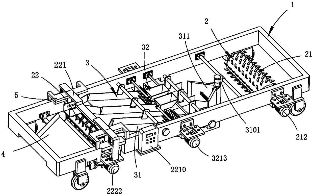
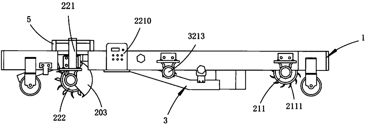
[0064] Such as figure 1 , figure 2 and image 3 As shown, a kind of automatic soil covering equipment for uniform fertilization, including walking carrier 1, also includes:

[0065] The soil loosening part 2, the soil loosening part 2 is installed on the walking carrier 1, which includes a shallow soil loosening device 21 installed at the front part of the walking carrier 1, a deep layer loosening device 21 installed at the rear part of the walking carrier 1 Soil loosening device 22, described shallow soil loosening device 21 carries out soil loosening work to the upper surface soil of land, and described deep layer loose soil device 22 is used for carrying out deep soil loosening operation to the land that finishes upper surface soil loosening operation , and move the loose deep soil backwards;

[0066] Soil transfer part 3, described soil transfer part 3 is installed on the described walking carrier 1, and it is positioned between described shallow layer loosening device...

Embodiment approach

[0068] As a preferred embodiment, the shallow layer loosening device 21 includes

[0069] The first soil loosening part 211, the first soil loosening part 211 is horizontally rotated and installed on the walking carrier 1, and a plurality of first soil loosening rake teeth 2111 are arranged around the outer peripheral surface equidistantly along the axial direction;

[0070] The first power part 212, the first power part 212 is fixedly arranged on the walking carrier 1, which drives the first soil loosening part 211 to perform soil loosening work;

[0071] Described deep layer loosening device 22 comprises

[0072] Lifting mechanism 221, the lifting mechanism 221 is installed on the walking carrier 1, which includes a lifting cylinder 2211 symmetrically arranged on the walking carrier 1 and a support frame 2212 that moves up and down under the synchronous drive of the lifting cylinder 2211;

[0073] The deep layer loosening mechanism 222, the deep layer loosening mechanism 22...

Embodiment 2

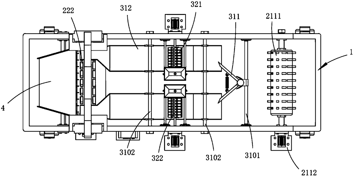
[0107] In order to evenly spread the upper surface soil transported by the soil transfer part on the deep soil, this example also provides an implementation, wherein the same or corresponding parts as in Example 1 use the corresponding drawings of Example 1 Marking, for the sake of brevity, only the differences from Embodiment 1 will be described below. The difference between this embodiment two and embodiment one is:

[0108] As a preferred embodiment, the rear of the deep soil loosening device 22 is also fixedly provided with a receiving plate 4 for receiving the upper surface soil output by the soil transfer part 3 backward;

[0109] It should be noted here that the output ends of the first conveying trough 3121 and the second conveying trough 3122 are gradually retracted to both sides to make room for the second soil loosening member 2221 to throw soil. The first conveying trough 3121 and the second conveying trough 3121 The upper surface soil output by the groove 3122 fa...


PUM


Abstract

The invention relates to uniform-fertilizing automatic earthing equipment which comprises a traveling carrier, a soil loosening portion and a soil transferring portion. The soil loosening portion andthe soil transferring portion are mounted on the traveling carrier, the soil loosening portion comprises a shallow-layer soil loosening device and a deep-layer soil loosening device, the soil transferring portion is arranged between the shallow-layer soil loosening device and the deep-layer soil loosening device and comprise a conveying device for transferring upper-surface-layer loose soil generated by the shallow-layer soil loosening device during soil loosening and a soil-moving fertilizing device arranged above the conveying device and used for pushing and fertilizing soil. The soil transferring portion transfers the fertilized loose upper-surface-layer soil onto the deep-layer soil after going through deep-layer soil loosening, and the deep-layer soil loosening device transfers the deep-layer soil as covering soil onto the upper-surface-layer soil at the same time to enable fertilizer to be completely integrated into the soil, so that loss and waste are avoided, land resources areutilized reasonably, and vegetation growth is facilitated.

Description

technical field [0001] The invention relates to the technical field of agricultural machinery and equipment, in particular to an automatic soil covering equipment for uniform fertilization. Background technique [0002] At present, fertilizer applicators are divided into solid chemical fertilizer applicators and liquid fertilizer applicators. Solid fertilizer applicators are divided into two types: fertilizer spreading machines and seed fertilizer applicators. Fertilizer spreading machines are divided into centrifugal fertilizer spreaders, full width fertilizer spreaders and pneumatic There are three kinds of wide-width fertilizer spreaders, among which the centrifugal fertilizer spreader is the most commonly used spreading machine in Europe and the United States. Fertilizers will not lose their effectiveness when exposed to the sun, and it is necessary to cover the land after fertilization, which makes fertilization inefficient and increases the workload of operators. [0...

Claims


Application Information

Patent Timeline
IPC IPC(8): A01B49/06
CPCA01B49/06
Inventor 徐海军
Owner 台州市智诚工业设计有限公司
Why Eureka
Try Eureka